

 English
 中文简体
中文简体
 русский
 Español

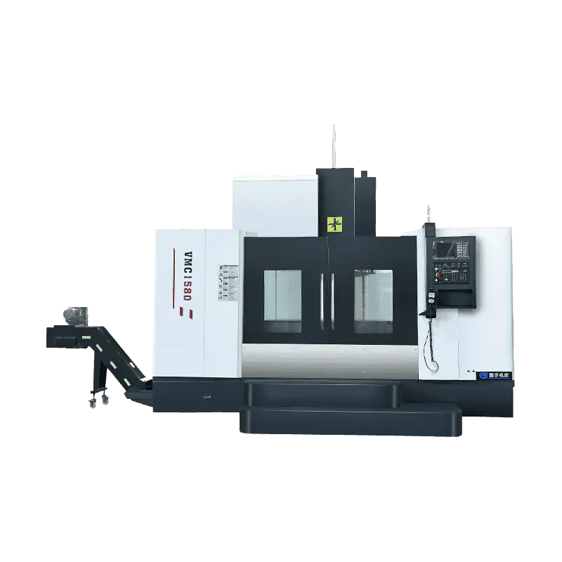
Technical Characteristics: The machine tool is a single-column vertical guideway structure. The colu...
See DetailsEquipment selection in precision machining rarely comes down to a single variable. When a facility is evaluating whether to invest in a horizontal or vertical CNC lathe configuration, the decision touches spindle orientation, workpiece geometry, floor layout, chip management, and long-term production throughput simultaneously. For operations handling heavy-duty turning work — large shafts, disc components, flanges, or high-volume automotive parts — the configuration choice directly determines machining stability, cycle time, and setup complexity. Before any equipment investment makes sense, one must understand what distinguishes these two machine types at a structural and operational level.
A horizontal CNC lathe positions the spindle axis parallel to the floor. The workpiece rotates along a horizontal axis while cutting tools mounted on a turret or cross-slide move along the X and Z axes to remove material. This configuration is the more widely used layout in general turning work, particularly for shaft-type components and cylindrical parts where length significantly exceeds diameter.
The horizontal layout creates a natural gravity path for chips — they fall away from the cutting zone and collect in a chip conveyor below the work area. This keeps the cutting zone cleaner during extended runs and reduces the frequency at which operators need to clear swarf from the work envelope. For operations running continuous production shifts, that chip management advantage compounds over time.
Horizontal machines also tend to offer longer between-centers distances, which makes them the default choice for bar stock, pipe machining, long shaft turning, and any application where the part needs to be supported at both ends during the cut.
A vertical CNC lathe — often referred to as a vertical turning center or VTL — mounts the spindle axis perpendicular to the floor. The workpiece sits on a rotating table or chuck that faces upward, and the cutting tools approach from above. Gravity acts along the spindle axis rather than against it, which means large, heavy workpieces seat themselves against the chuck face under their own weight rather than being clamped laterally.
This configuration is particularly well suited to short, wide components — brake discs, pump housings, wheel hubs, flanges, and large-diameter rings — where the diameter is substantially greater than the height. Clamping a disc-type part in a horizontal spindle requires substantial radial clamping force to prevent the part from deflecting under gravity. In a vertical configuration, the same part sits naturally on the table with no gravitational load working against the clamp.
Vertical machines also occupy a smaller floor footprint per unit of workpiece diameter, because the machine height absorbs what would otherwise be lateral floor space in a horizontal layout. For shops working with large-diameter components in a constrained building footprint, this spatial advantage can be decisive.
The spindle orientation is the visible starting point, but the structural consequences run deeper than a 90-degree rotation.
Workpiece loading and clamping: In a horizontal lathe, the operator loads the part through the chuck face from the front or the side, often with the assistance of a tailstock for long components. In a vertical lathe, the part is lowered onto the rotating table — typically with an overhead crane for heavy components — and the clamping force is applied radially outward from the table center. The loading method shapes the fixturing strategy, the cycle time per part, and the ergonomic demands on the operator.
Gravity and deflection: In a horizontal configuration, gravity acts radially on the workpiece. For a long, heavy shaft, this creates a sag between the chuck and the tailstock that must be compensated through steady rests or support fixtures, particularly in finishing passes where deflection affects dimensional accuracy. In a vertical configuration, gravity acts axially — downward into the table — which simplifies support for disc-type parts but introduces a different deflection mode in tall workpieces that extend significantly above the table surface.
Thermal behavior: Horizontal machines generate heat through cutting and drive systems that distributes differently through the machine structure than in vertical machines. Both configurations require thermal compensation strategies in precision applications, but the paths of thermal growth differ by orientation.
Chip evacuation: Horizontal configurations benefit from gravity-assisted chip fall. Vertical configurations, where the cutting zone faces upward, require more deliberate chip management — coolant flow, chip conveyors, and cover systems — to prevent chips from accumulating on the rotating table or within the work envelope.
| Feature | Horizontal CNC Lathe | Vertical CNC Lathe |
|---|---|---|
| Workpiece Type | Shafts, bars, cylindrical parts | Discs, flanges, large-diameter rings |
| Clamping Method | Radial chuck or collet with tailstock | Face plate or radial jaw on rotating table |
| Gravity Effect | Acts radially on workpiece | Acts axially, aids seating on table |
| Chip Evacuation | Natural gravity fall | Requires active management |
| Floor Footprint | Longer, proportional to between-centers | More compact per unit of workpiece diameter |
| Setup for Heavy Parts | Requires support fixtures | Crane loading, gravity-assisted clamping |
| Precision on Long Parts | Requires steady rest for long shafts | Not suited for long slender parts |
| Precision on Large Discs | Requires substantial radial clamping | Naturally stable under gravity |
| Automation Integration | High — bar feeders, robot loading | Moderate — crane or gantry required |
| Typical Industries | Automotive, aerospace, general turning | Energy, heavy industry, automotive discs |
The table reflects operational tendencies rather than absolute limits. Capability overlaps in both directions — a well-specified horizontal machine can handle certain disc components, and some vertical machines are configured for shaft work — but the tendencies above reflect where each configuration delivers more consistent results with fewer compromises.
Horizontal CNC lathes are specified for applications where part length is a primary variable:
Vertical CNC lathes are specified for applications where diameter and mass are the primary variables:
The distinction between standard and heavy-duty turning work is not simply a question of part size. Heavy duty CNC lathe machine requirements involve higher cutting forces, longer cycle times, greater thermal accumulation in the machine structure, and more demanding requirements for spindle rigidity, bed construction, and tool holding.
In horizontal heavy-duty turning, the primary structural requirements are:
In vertical heavy-duty turning, the requirements shift:
For facilities evaluating a new CNC heavy duty lathe against existing equipment, the structural comparison goes beyond stated swing and between-centers capacity. The rigidity of the machine base, the quality of the guideways, and the thermal compensation system determine whether the machine performs at specification under sustained production loads or only under controlled test conditions.
The decision framework is cleaner than it might appear when stated in terms of part geometry rather than machine features.
Choose a horizontal configuration when:
Choose a vertical configuration when:
Consider both configurations when:
The cost differential between horizontal and vertical machines of comparable capacity varies by specification level, and neither type carries a universal price advantage over the other. The investment decision is better framed around the cost of compromised setups — additional fixturing, multiple operations, extended cycle times — when the wrong machine type is used for a part family it was not designed to handle efficiently.
Efficiency comparisons between horizontal and vertical CNC lathes are often framed as head-to-head metrics, but the more accurate frame is configuration-to-application match. A horizontal machine running shaft parts it is well suited for will outperform a vertical machine running the same parts in a configuration that was not designed for them — and vice versa.
The operating factors that accumulate significance over a machine's service life include:
Setup time: A poorly matched machine-to-part combination requires additional fixturing, more operator intervention between cycles, and longer verification steps. Over months of production, that added setup time represents a material reduction in available cutting time.
Tooling wear patterns: Machines running parts they are configured for maintain more consistent tool engagement — cutting forces act in directions the structure is designed to resist. Inconsistent tool engagement accelerates wear and increases the frequency of tool changes, which interrupts production and adds consumable cost.
Maintenance intervals: Heavy-duty machines running near their structural limits require more frequent inspection of guideways, spindle preload, and coolant systems than machines running at moderate capacity. Selecting a machine with adequate capacity margin — rather than a machine sized exactly to the largest anticipated part — extends maintenance intervals and reduces unplanned downtime.
Operator ergonomics and safety: A vertical machine loading heavy disc components via overhead crane has a different safety and ergonomics profile than a horizontal machine loading bar stock through a bar feeder. Both are manageable, but neither is zero-effort. Planning the cell layout around the loading method — rather than adapting the loading method to an existing layout — reduces operator fatigue and handling risk over the machine's working life.
For facilities in the market for a new machine, the distinction between purchasing from a CNC lathe factory directly and purchasing through a CNC lathe supplier carries practical consequences that go beyond unit price.
A direct factory relationship typically offers:
A supplier or distributor relationship offers:
Neither channel is categorically preferable — the decision depends on how standardized the required machine is, how critical the timeline is, and whether the facility's engineering requirements are within the factory's standard product range or require customization.
For procurement teams evaluating suppliers, the questions worth asking are: Does this source manufacture the machine or assemble from purchased components? What is the delivery timeframe for a non-standard configuration? What after-sales support is accessible in the facility's region? Can the supplier share reference installations that run comparable part families?
Framing the comparison between horizontal and vertical CNC lathe configurations around three questions yields a clean resolution: What does the part look like? How heavy is it? And what does the production environment require? A long shaft runs better horizontally. A heavy disc runs better vertically. A facility processing both needs to decide whether the volume justifies two dedicated configurations or whether a single machine with compromised performance on one part type is the more practical choice at current production scale. For facilities at the procurement stage — evaluating machine specifications, comparing factory capabilities, or planning a production cell around a defined part family — the practical next step is engaging with a manufacturer who can provide technical documentation, reference part cutting trials, or machine demonstration at scale. Zhejiang Guoyu CNC Machine Tool Co., Ltd. manufactures horizontal and vertical CNC turning centers for industrial applications, with engineering support for non-standard configurations, heavy-duty specifications, and custom tooling arrangements. Contacting the team to discuss part geometry, production volume, and configuration requirements is the appropriate starting point for buyers who need a machine matched to a specific application rather than a catalogue selection.
Technical Characteristics: The machine tool is a single-column vertical guideway structure. The colu...
See Details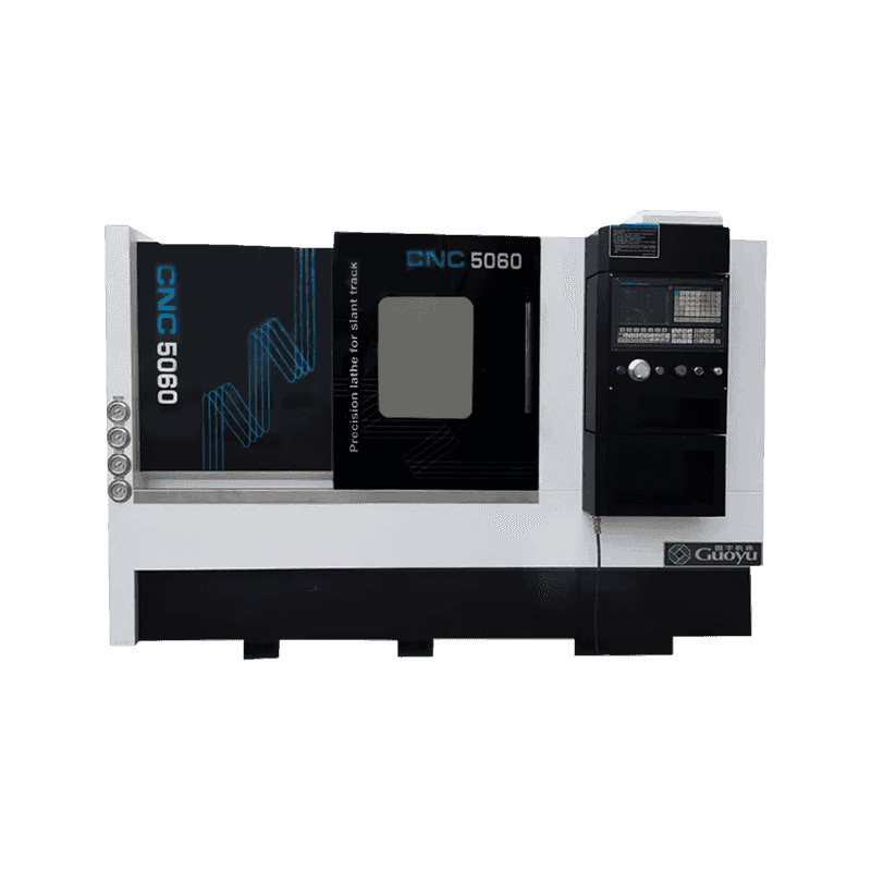
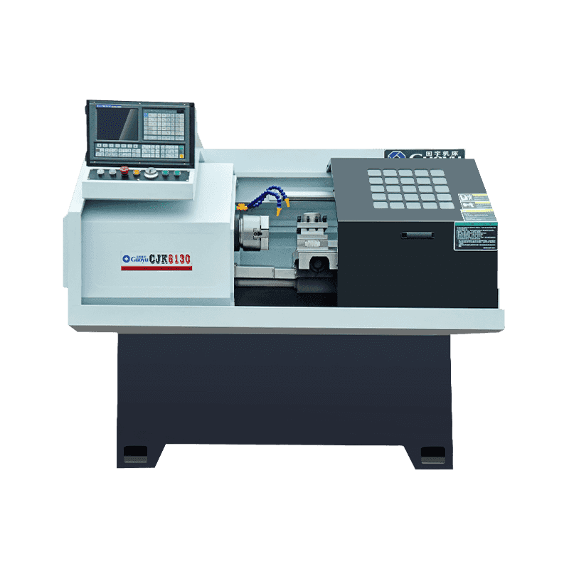
Technical Characteristics: The machine tool is of high precision, and the spindle is supported by hi...
See Details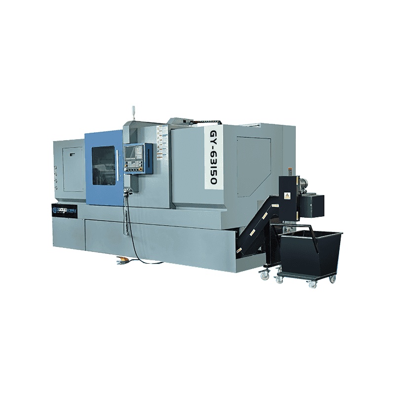
Technical Characteristics: The transmission adopts the linear rolling guide imported from Taiwan to ...
See Details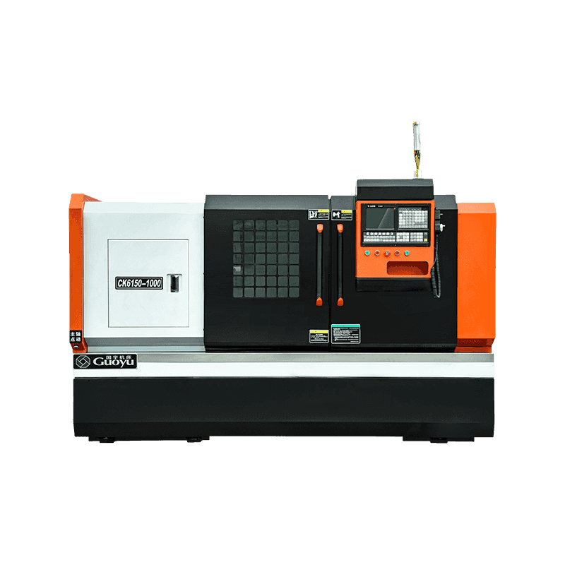
Technical Characteristics: It can automatically turn all kinds of turning surfaces, such as cylinder...
See Details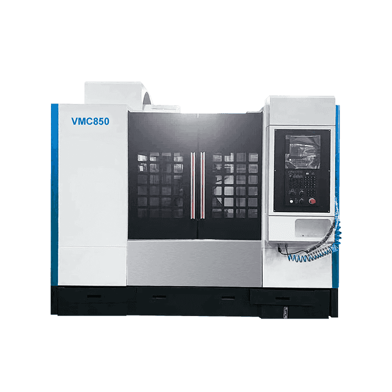
Technical Characteristics The machine tool is a single-column vertical guideway structure. The colum...
See Details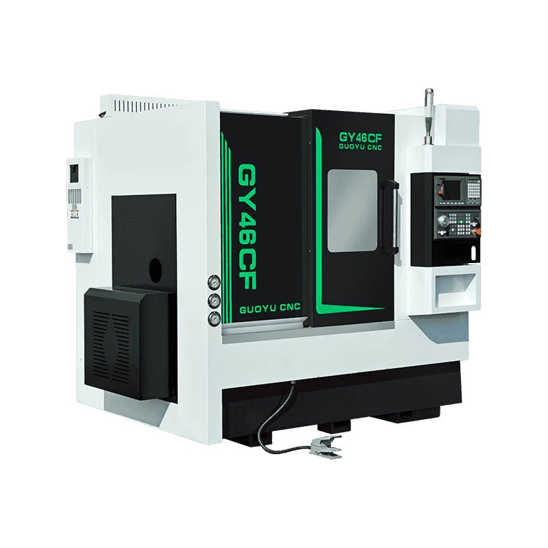
Technical Characteristics: 45° slant bed base structure, with strict aging treatment, smooth chip re...
See Details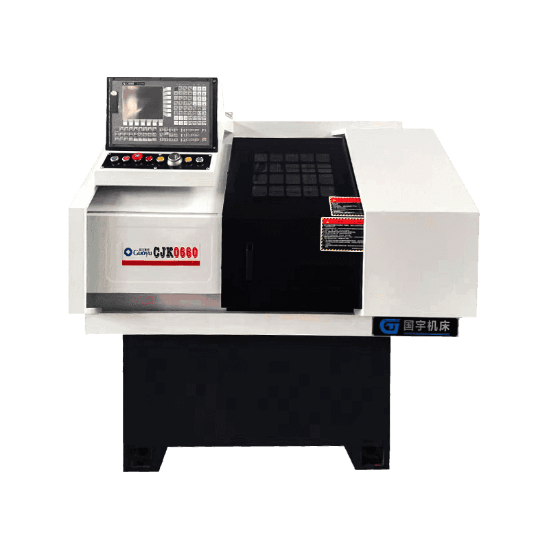
We take pride in presenting our CJK-0660 Custom Precision Line Rail Precision CNC Lathe, a robust an...
See Details
Technical Characteristics: It can cut all kinds of turning surfaces by bicycle, such as conical surf...
See DetailsOur team of digital and business experts will guide you to the right direction.
Let's TalkZhejiang Guoyu CNC Machine Tool Co., Ltd. relies on rich experience, professional technology and advanced methods to ensure the quality of its products, so that customers can enjoy more professional and thoughtful service.
 [email protected]
 +86-15356565970
 Xialiang Industrial Area, Luqiao District, Taizhou City, Zhejiang Province, China
Copyright © Zhejiang Guoyu CNC Machine Tool Co., Ltd. All Rights Reserved.