English
 中文简体
中文简体 русский
 Español

Technical Characteristics: The CNC machine tool for inclined beds adopts the domestic or imported hi...
See Details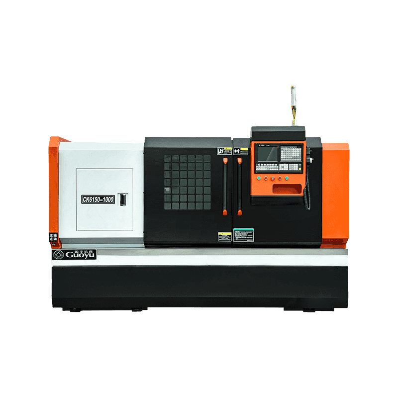
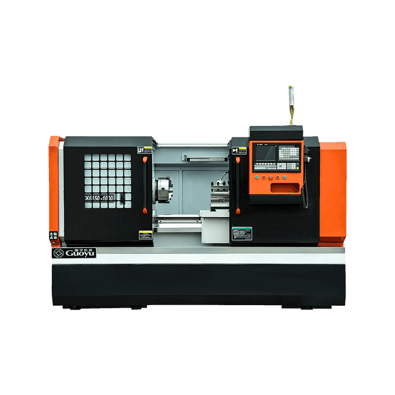
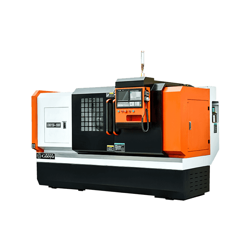
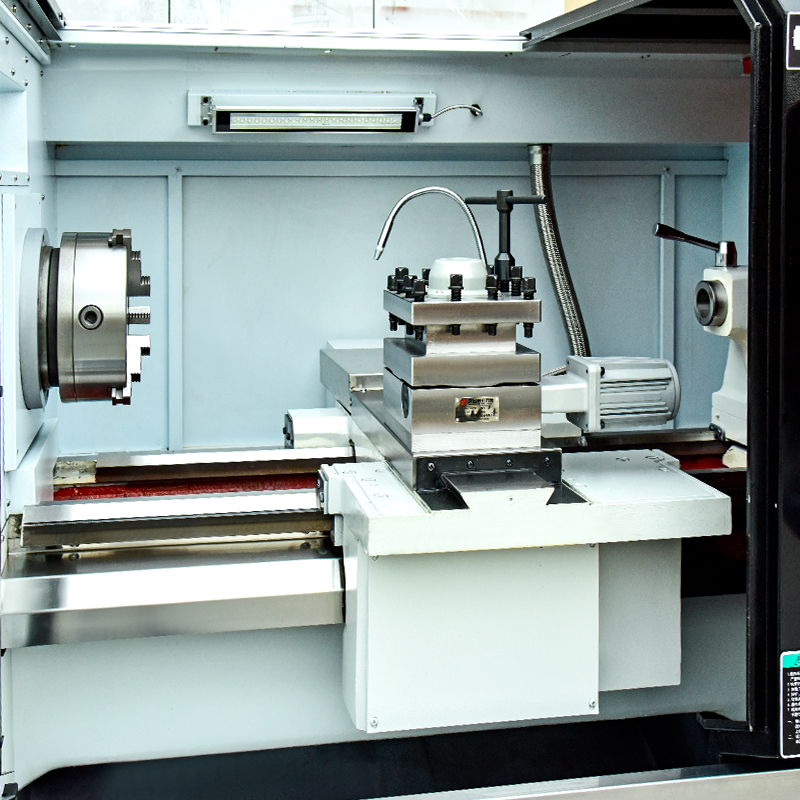
The Heavy Cutting Hard Guideway CNC Lathe For Metal Cutting is a really tough, heavy-duty machining solution built for deep cuts and high-volume metal turning jobs on the shop floor. Going with hardened and precision-ground box ways makes a big difference because it gives you plenty of raw rigidity and stable backbone support when you are wrestling with larger, demanding workpieces. The reinforced headstock and carriage assembly add a ton of structural strength, letting you hog off surplus material efficiently without throwing a fit.Its four-position electric tool turret uses a precise toothed-disc clamping setup for completely reliable, repeat tool indexes, while the electronic handwheel gives your operators a handy, convenient way to set up tools on the fly. Packed with a high-power coolant pump for effective heat and chip wash, this CNC lathe handles turning cylinders, cones, cutting grooves, tracking threads, internal boring, reaming tasks, and other complex metal components smoothly day shift after day shift.
| Projects | unit | CK6150-1000 | |
| PROCESSING CAPACITY | Maximum turning diameter of bed | mm | 520 |
| Maximum rotary diameter of support plate | mm | 290 | |
| Maximum machining length | mm | 1000 | |
| MAIN SHAFT | Spindle end form | \ | A2-8 |
| Diameter of main shaft through hole | mm | 82 | |
| Maximum rod passing diameter | mm | 80 | |
| Maximum spindle speed | r/min | 1600 | |
| Spindle shift mode | \ | Three-speed gear variable speed/frequency conversion | |
| Main motor power | kw | 7.5 | |
| Chuck type | \ | Manual (standard) / hydraulic chuck (optional) | |
| Chuck size | inch/mm | 10 | |
| FEED | X-axis stroke | mm | 500 |
| Z-axis stroke | mm | 1000 | |
| X-axis fast-moving velocity | m/min | 8 | |
| Z-axis fast-moving velocity | m/min | 10 | |
| X-axis motor torque | N·m | 5.5 | |
| Z-axis motor torque | N·m | 10 | |
| Type of rail | \ | Hard rails | |
| X-axis guide rail specifications | mm | \ | |
| Z-axis guide rail specifications | mm | \ | |
| X-axis made screw specification | mm | 2505 | |
| Z-axis made screw specification | mm | 4010 | |
| TOOL REST | Tool rest type | \ | 4-station electric turret |
| Square tool/Boring tool size | mm | 25*25/φ32 | |
| TAIL SEAT | Tail seat form | \ | Manual tailstock |
| Tail seat sleeve taper | \ | MT-5 | |
| Tail seat sleeve diameter | mm | 75 | |
| Tail seat sleeve stroke | mm | 150 | |
| OTHER | Machine tool size (length* width* height) | mm | 2700*1600*1750 |
| Machine weight | kg | 2800 | |
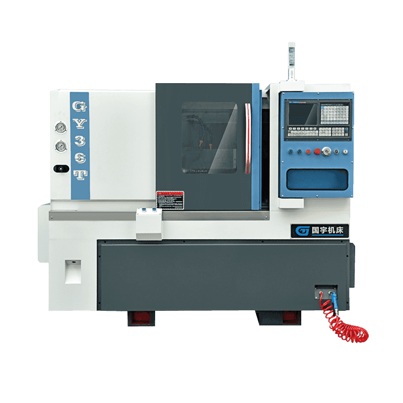
Technical Characteristics: The CNC machine tool for inclined beds adopts the domestic or imported hi...
See Details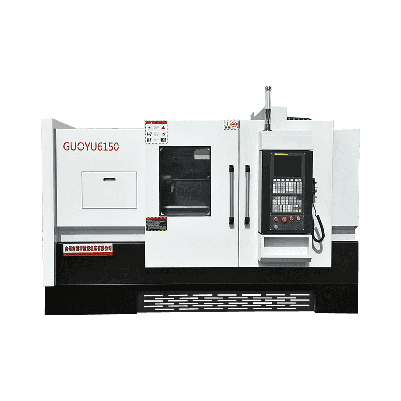
Technical Characteristics: It can cut all kinds of turning surfaces by bicycle, such as conical surf...
See Details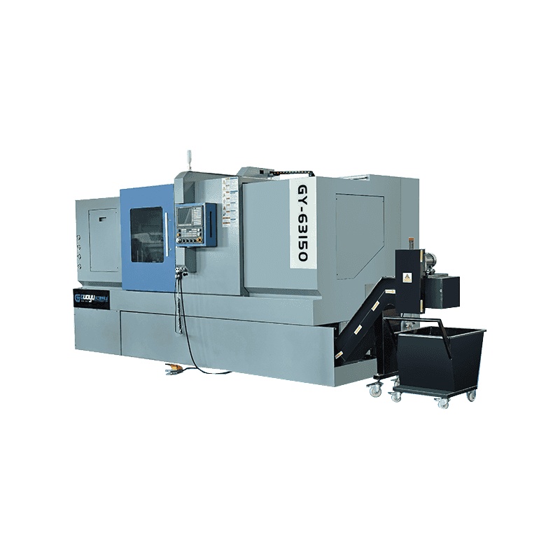
The Precision CNC Lathe With Programmable Tailstock For Connected Inclined Rail Tool Tower is just a...
See Details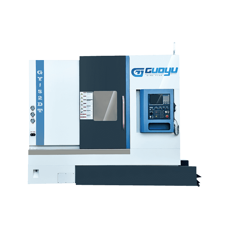
Technical Characteristics: The CNC machine tool for inclined beds adopts the domestic or imported hi...
See Details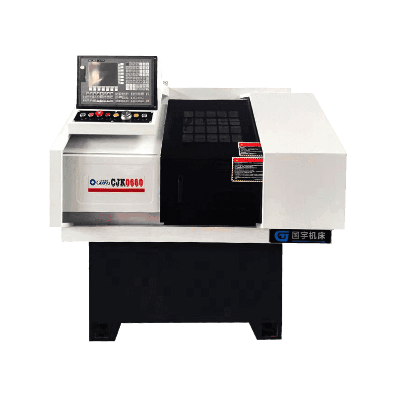
The Custom Precision Line Rail Precision CNC Lathe is just a really practical, compact machining sol...
See Details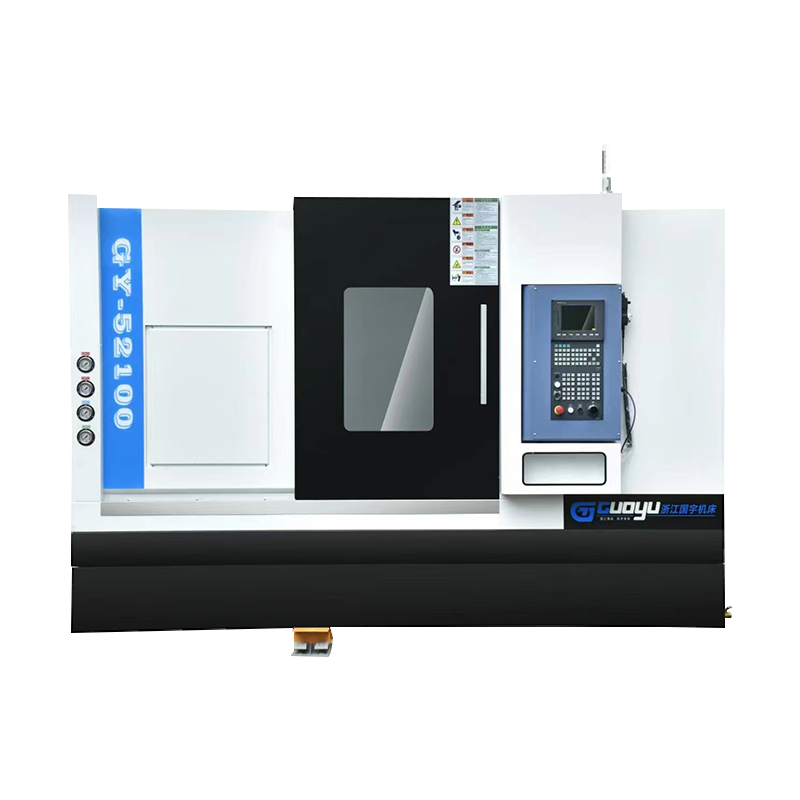
Technical Characteristics:Line Rail CNC lathes are integrally cast with 250 materials to ensure proc...
See Details
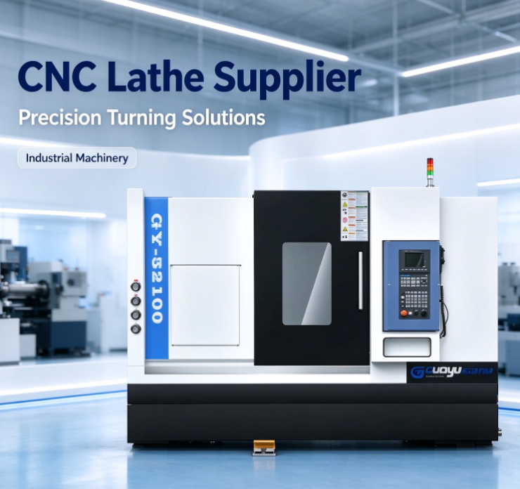
Choosing a CNC lathe supplier takes more than comparing machine features and prices. A CNC lathe sits inside a larger production process. It shapes workflow...
READ MORE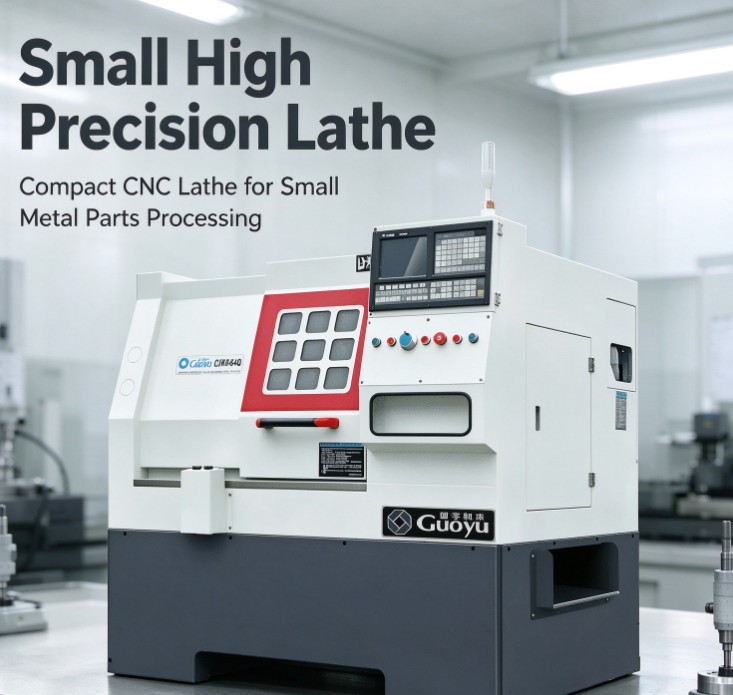
Small components quietly carry a lot of weight across manufacturing. They show up in instruments, mechanical assemblies, electronic equipment, medical devic...
READ MORE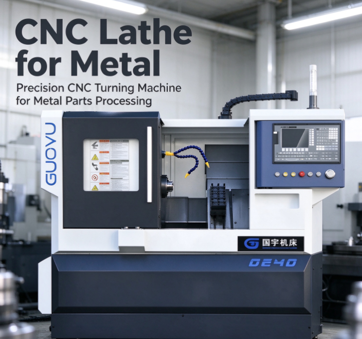
Metal parts show up in almost every corner of modern manufacturing. They form the shafts inside machines, the fittings in plumbing systems, the connectors i...
READ MOREA twin turret CNC automatic lathe machine is a computer-controlled turning center that carries two independent tool turrets instead of the usual one. Each turret holds multiple cutting tools—usually 8 to 12 stations per turret—and both can engage the workpiece at the same time. “Automatic” means the machine handles bar feeding, tool changes, and part cutoff without an operator standing there.
The twin turret design is not new, but it's become much more common in Western job shops over the last five years. Why? Because labor costs keep rising, and cycle time reduction is one of the few levers left to stay competitive.
The basic idea is simple: while one turret roughs the outside diameter, the second turret drills or bores from the opposite side, or works simultaneously on different diameters. But the real features go deeper than just “two turrets instead of one.” Let me walk you through what actually matters.
Independent turret motion with collision avoidance
This is the feature that separates a good twin turret machine from a bad one. Each turret moves on its own axis (typically X and Z for the main turret, plus possibly Y and a second Z for the subspindle turret). But here's the hard part: the two turrets share the same workspace. Without intelligent collision monitoring, they'd crash into each other or into the workpiece.
Modern twin turret lathes from builders like DMG MORI, Nakamura-Tome, and Takamaz use software-based interference checking. The control (often a Fanuc 31i or Siemens 840D) maps the tool positions in real time and prevents moves that would cause a collision. Some systems even let you program “virtual walls” so the turrets stay in their assigned zones.
Why this matters for a shop owner: you can program both turrets to cut simultaneously without spending hours on manual clearance checks. That's where the cycle time savings come from.
Balanced cutting for difficult materials
When you machine a long, slender shaft or a thin-walled tube, cutting forces from a single tool can push the workpiece away from center. That causes taper, chatter, or out-of-round parts.
With twin turrets, you can program them to cut opposite sides of the part at the same time. One turret takes a cut at 12 o'clock, the other at 6 o'clock. The cutting forces cancel each other out. The workpiece stays centered. You can take deeper cuts and higher feed rates without deflection.
This is a huge deal for aerospace shops running Inconel or titanium, or for medical device shops turning thin bone screws. A single turret machine might need three finishing passes to hit roundness within 0.0005 inches. A twin turret machine does it in one simultaneous pass.
Subspindle and part transfer integration
Almost every twin turret automatic lathe includes a subspindle (sometimes called a secondary spindle or pick-off spindle). The main spindle holds the bar stock. The subspindle faces the main spindle from the opposite end.
Here's the typical sequence: The main turret machines the front side of the part. Then the subspindle advances, grips the part, and pulls it out of the main spindle collet. Now the subspindle holds the part, and the second turret (usually mounted on the subspindle side) machines the back side. Meanwhile, the main spindle is already cutting the next part from the bar.
That overlap is where the “automatic” name pays off. You get complete machining of a part—front and back—in one cycle with no operator reloading. Cycle times drop from minutes to seconds for small turned parts.
Let me paint a picture that shows all these features working together.
The shop: A contract manufacturer in the Midwest. They won a five-year contract to produce stainless steel sensor housings for an automotive tier-one supplier. Volume is 15,000 parts per month. Each part is 1.5 inches long, 0.75 inches in diameter, with a threaded bore on one end, a cross hole, and an external hex.
Before twin turret: They run the job on two single-turret lathes and one milling machine. First lathe turns the OD and drills the bore. Operator unloads, moves parts to second lathe for threading. Then to a milling machine for the hex and cross hole. Labor cost is high. Work-in-progress inventory piles up between operations. Scrap rate is 4% from handling damage.
After twin turret: They buy a used twin turret automatic lathe with subspindle and live tooling. Programming takes two days. But once running, the machine does everything:
Cycle time per part: 22 seconds. Scrap rate: under 1%. One operator runs two machines because each machine runs unattended for 45 minutes between bar changes. Labor cost per part drops by 70%. The shop pays off the used machine in eleven months.
That's not a hypothetical. That's a real job I saw at a shop outside Cleveland. The owner told me, “I should have bought a twin turret five years ago.”

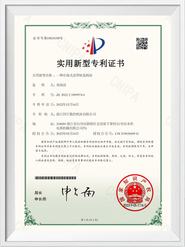
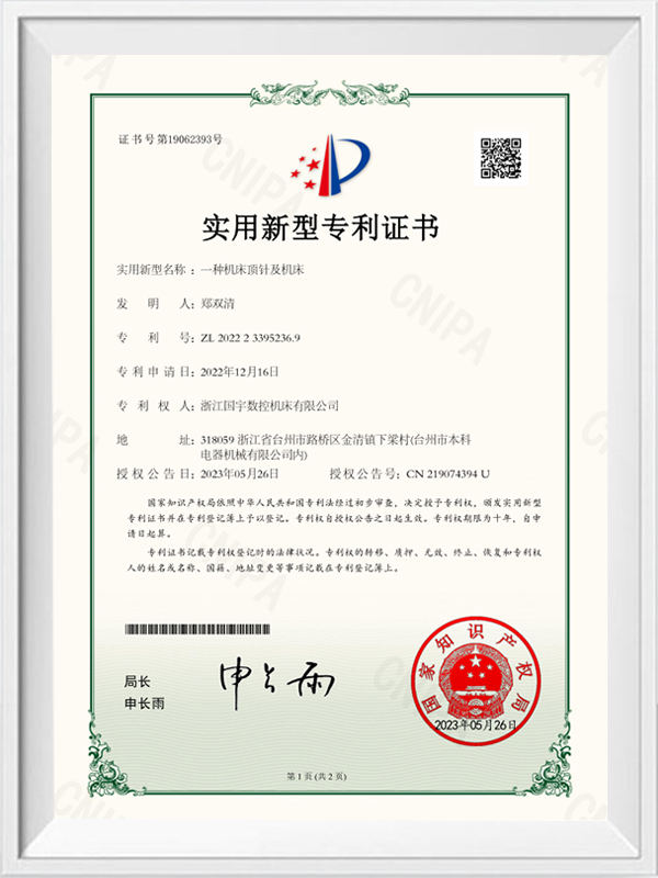
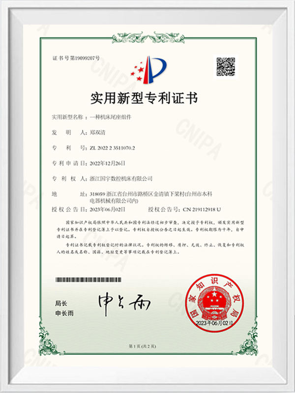
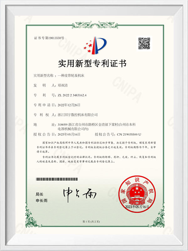
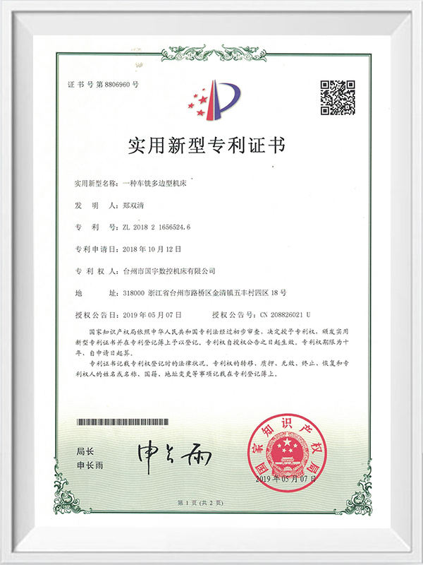
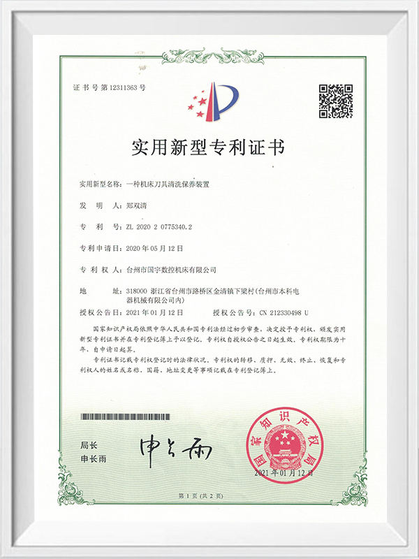
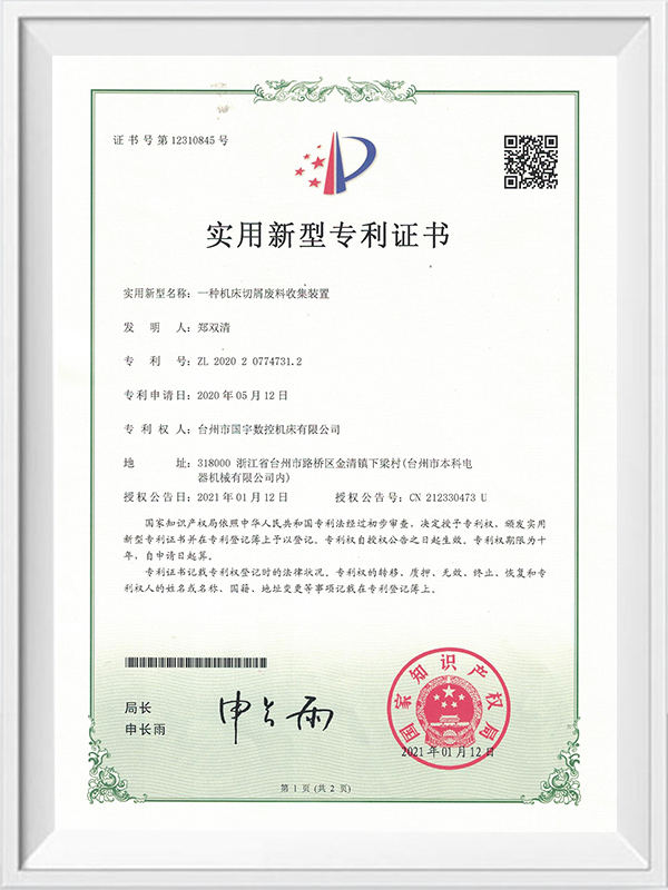
Zhejiang Guoyu CNC Machine Tool Co., Ltd. relies on rich experience, professional technology and advanced methods to ensure the quality of its products, so that customers can enjoy more professional and thoughtful service.
 [email protected]
 +86-15356565970
 Xialiang Industrial Area, Luqiao District, Taizhou City, Zhejiang Province, China
Copyright © Zhejiang Guoyu CNC Machine Tool Co., Ltd. All Rights Reserved.

Wholesale Heavy Cutting Hard Guideway CNC Lathe For Metal Cutting Suppliers