

 English
 中文简体
中文简体
 русский
 Español

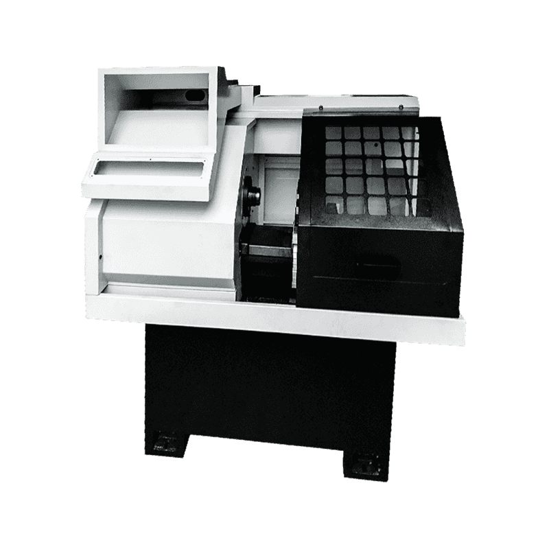
Technical Characteristics: It can cut all kinds of turning surfaces by bicycle, such as conical surf...
See DetailsA precision CNC lathe for small parts is a computer-controlled turning machine designed to machine workpieces with diameters typically under 50 mm and lengths under 100 mm. These lathes achieve tolerances of ±0.002 mm to ±0.005 mm, which is two to three times finer than standard CNC lathes (typically ±0.010 mm). They are used in the production of medical bone screws, dental implants, electronic connector pins, watch components, and fuel system parts. Spindle speeds range from 6,000 to 15,000 RPM, allowing the use of small-diameter cutting tools (3–12 mm) at surface speeds.
The ability to hold tolerances of ±0.002 mm requires specific design elements not found in general-purpose lathes. The following features are standard on precision small-parts lathes.
Thermal stability systems. Heat from spindle bearings, motors, and cutting processes causes expansion of steel components. A 300 mm-long cast iron bed expands by approximately 0.003 mm per °C rise in temperature. To control this, precision lathes incorporate spindle cooling—circulating coolant through a jacket around the spindle housing, maintaining temperature within ±1°C of ambient. Additionally, the machine bed is often made from polymer concrete (epoxy granite), which has a thermal expansion coefficient of 12 μm/m°C, compared to 11.7 μm/m°C for cast iron. While similar numerically, polymer concrete absorbs temperature changes more slowly due to its lower thermal diffusivity (0.6 mm²/s vs. 12 mm²/s for cast iron), meaning the bed takes 10–15 times longer to reach thermal equilibrium. This reduces dimensional drift during warm-up.
High-precision spindle bearings. Small-part lathes use angular-contact ceramic ball bearings (hybrid bearings) with steel rings and silicon nitride balls. Ceramic balls are 60% lighter than steel, reducing centrifugal force at high speeds. At 12,000 RPM, steel balls generate 300 N of centrifugal load on the outer race, while ceramic balls generate 120 N. A lower force reduces bearing heating and allows preload to be maintained. Spindle runout (radial deviation) is specified at 0.001 mm or less, measured at the taper seat. For comparison, a standard CNC lathe spindle has runout of 0.003–0.005 mm.
Linear guideways with preload. Precision lathes use roller-type linear guides (instead of ball type) because rollers provide line contact rather than point contact. A roller guide has a stiffness of 500–800 N/μm, compared to 200–300 N/μm for a ball guide of the same size. The guides are mounted with negative clearance (preload of 0.03–0.05 mm), eliminating play. The slide ways are covered with stainless steel telescopic covers to prevent swarf from entering the bearing blocks.
Direct-drive servo motors. Instead of using a ballscrew coupled to a motor via a timing belt (which introduces backlash of 0.005–0.015 mm), precision lathes often use direct-drive linear motors or high-lead ballscrews with dual preloaded nuts. A linear motor eliminates mechanical transmission, achieving positioning accuracy of ±0.0005 mm. However, linear motors cost $5,000–$10,000 per axis, so economical precision lathes use a ground ballscrew (C3 or C5 grade, error ≤0.008 mm per 300 mm) with a preloaded double nut.
The performance of a precision small-parts lathe is quantified by several measurable metrics. The table below summarizes typical values.
|
Accuracy Parameter |
Typical Value (Precision Lathe) |
Value (Standard Lathe) |
Measurement Method |
|
Positioning repeatability |
±0.001 mm |
±0.005 mm |
Laser interferometer over 50 mm travel |
|
Spindle runout (at taper) |
0.0008–0.0012 mm |
0.003–0.005 mm |
Dial indicator on test arbor |
|
Roundness of machined part |
0.001–0.002 mm |
0.005–0.010 mm |
Roundness tester (50 points/revolution) |
|
Surface finish (Ra, turning aluminum) |
0.2–0.4 μm |
0.8–1.2 μm |
Contact profilometer |
|
Diameter tolerance capability |
±0.002 mm (Cpk ≥1.33) |
±0.010 mm |
Statistical analysis of 30 parts |
Factors affecting roundness. Roundness error in turned parts comes from three sources: spindle bearing error (geometric runout), workpiece clamping distortion, and cutting force deflection. On a precision lathe, spindle error dominates at 0.0008 mm. Clamping distortion occurs when a collet applies uneven radial force. For a thin-wall part (wall thickness 0.5 mm), a clamping force of 2,000 N can deform the part by 0.005 mm. To avoid this, precision lathes use collets with 6–12 slots (instead of 3 slots) to distribute force evenly, or use expanding mandrels for internal clamping.
Surface finish limitations. While a precision lathe can achieve Ra 0.2 μm on aluminum, the same lathe on stainless steel (304) achieves only Ra 0.5–0.8 μm due to material build-up at the edge. The theoretical surface finish is calculated as Ra = (f²) / (32 × R), where f is the feed rate (mm/rev), and R is the tool nose radius (mm). For f = 0.02 mm/rev and R = 0.2 mm, theoretical Ra = (0.02²)/(32×0.2) = 0.0004/6.4 = 0.0000625 mm = 0.0625 μm. In practice, measured Ra is 3–5 times higher due to machine vibration and material properties. A measured Ra of 0.3 μm is considered for turning.
Machining small parts requires tooling scaled to the workpiece. Standard tooling for 20 mm diameter lathes does not fit 100 mm lathes.
Tooling dimensions. Precision small-parts lathes use tools with shank sizes of 10 mm × 10 mm or 12 mm × 12 mm, compared to 20 mm × 20 mm or 25 mm × 25 mm on standard lathes. Insert sizes are correspondingly smaller: for turning, the common insert is CCGT 06 02 04 (6 mm inscribed circle diameter, 2 mm thick) or TCGT 11 01 02 (11 mm for larger parts). The small size allows tool turrets to index faster (0.2–0.3 seconds per station) because the turret mass is lower. However, small inserts have shorter edge life: a CCGT 06 02 04 insert in 304 stainless steel lasts 15–20 minutes of cutting time, while a larger CNMG 12 04 08 insert lasts 60–90 minutes.
Workholding systems. Three types of workholding are common:
Pneumatic or hydraulic chucks with soft jaws. For parts with irregular shapes (hexagonal, square, or cast surfaces), soft jaws are machined to match the part contour. The chuck’s clamping force is adjustable from 500 N to 5,000 N. For small parts, excessive clamping force (above 2,000 N) is avoided because it can mark soft materials like brass or aluminum.
Magnetic and vacuum chucks. For non-ferrous parts, vacuum chucks hold thin discs (0.5–2 mm thick) without distortion. A vacuum chuck requires a smooth, flat part back surface. Holding pressure is approximately 90 kPa (0.9 bar), providing 90 N of holding force per 10 cm² of contact area. Sufficient for light finishing cuts (0.05–0.10 mm depth of cut).
Technical Characteristics: It can cut all kinds of turning surfaces by bicycle, such as conical surf...
See Details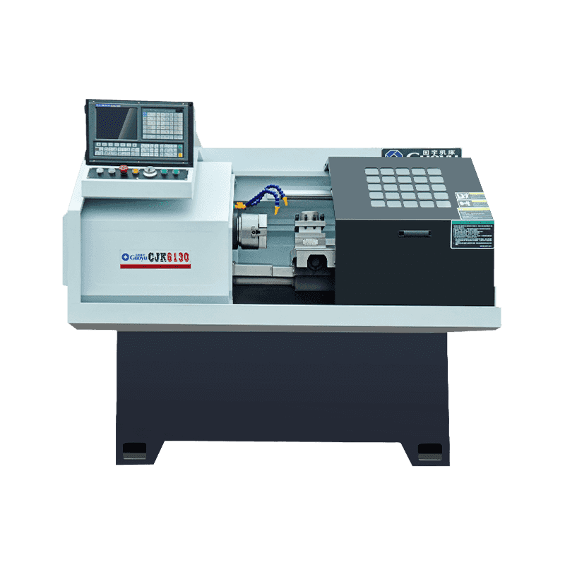
Technical Characteristics: The machine tool is a single-column vertical guideway structure. The colu...
See Details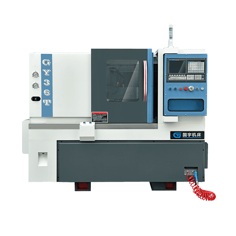
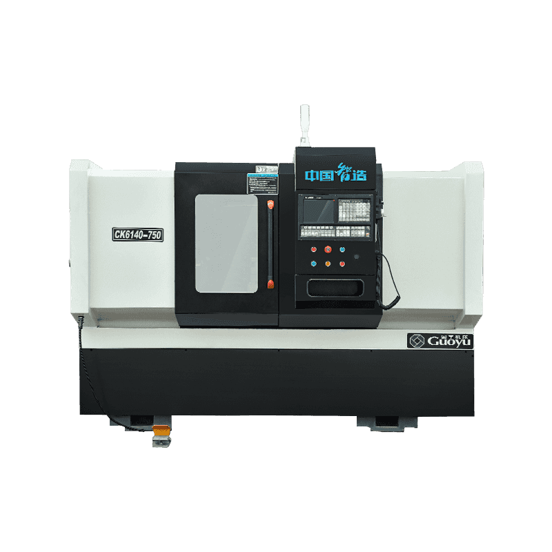
Technical Characteristics: The CNC machine tool for inclined beds adopts the domestic or imported hi...
See Details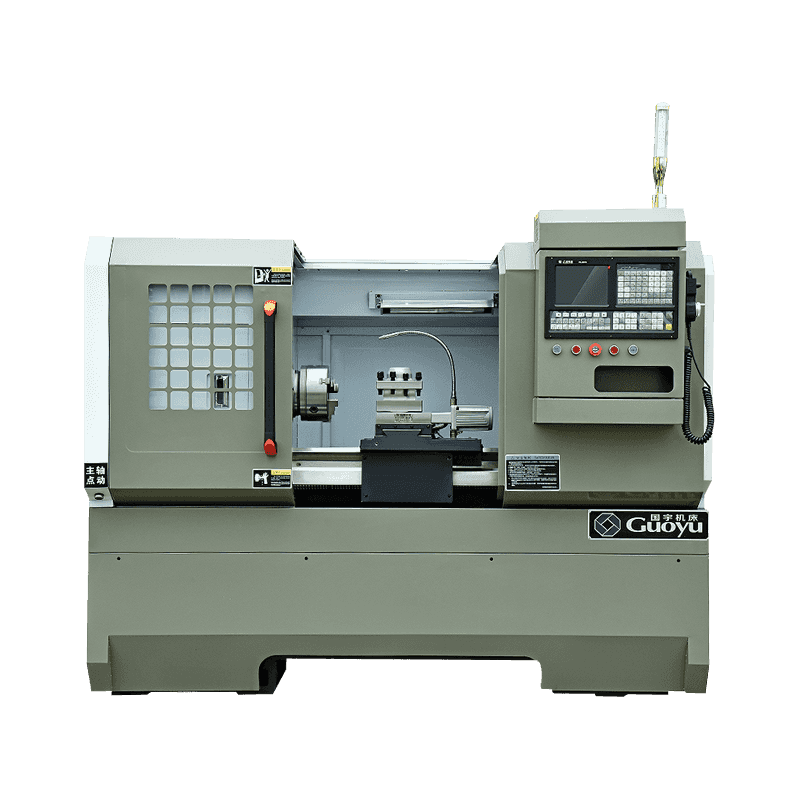
Technical Characteristics: It can cut all kinds of turning surfaces by bicycle, such as conical surf...
See Details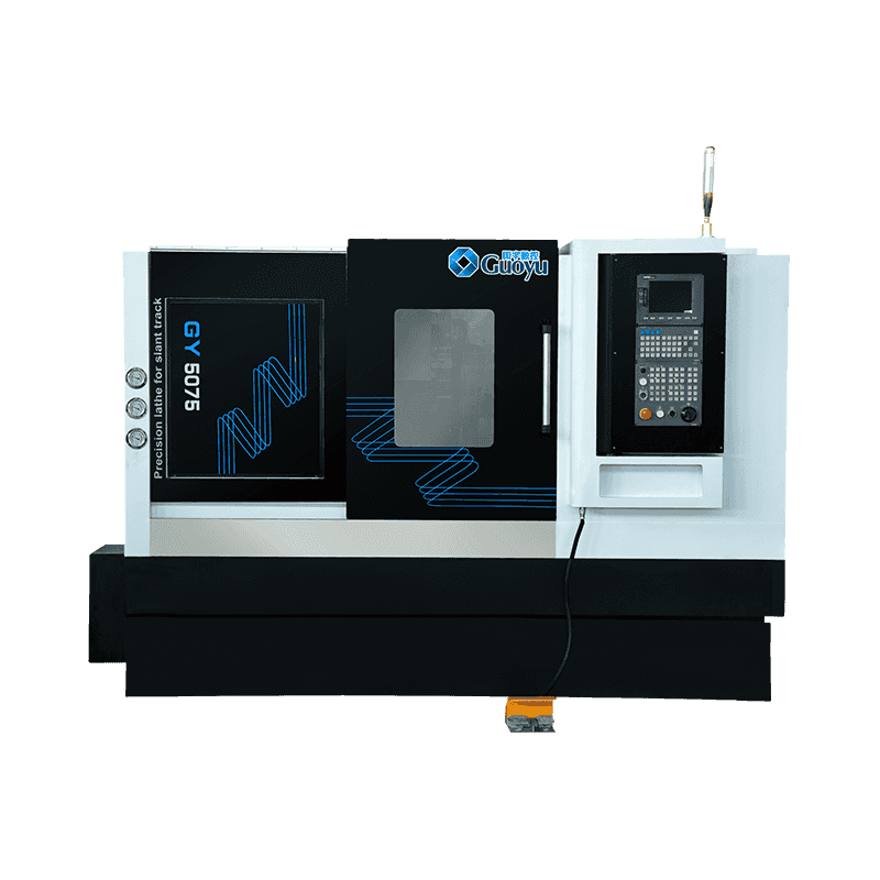
Technical Characteristics: The CNC machine tool for inclined beds adopts the domestic or imported hi...
See Details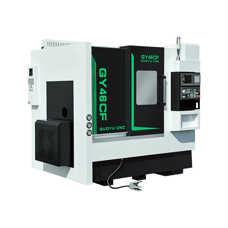
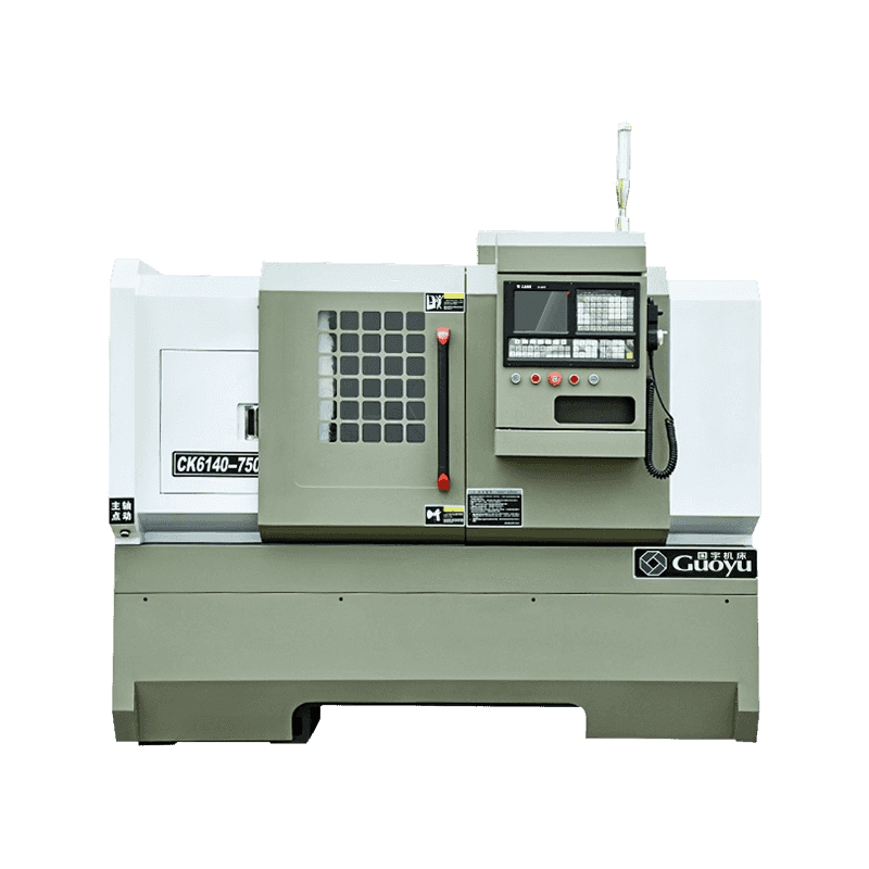
Technical Characteristics: 45° slant bed base structure, with strict aging treatment, smooth chip re...
See Details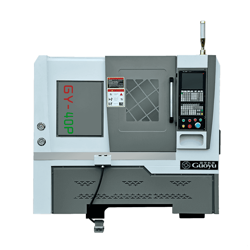
Technical Characteristics: 40P is a kind of small precision machine tool, that is suitable for the e...
See Details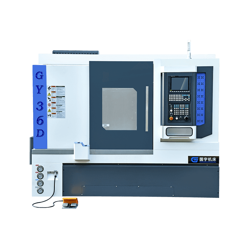
Technical Characteristics: All lathes are integrally cast with 250 materials to ensure processing ri...
See DetailsOur team of digital and business experts will guide you to the right direction.
Let's TalkZhejiang Guoyu CNC Machine Tool Co., Ltd. relies on rich experience, professional technology and advanced methods to ensure the quality of its products, so that customers can enjoy more professional and thoughtful service.
 [email protected]
 +86-15356565970
 Xialiang Industrial Area, Luqiao District, Taizhou City, Zhejiang Province, China
Copyright © Zhejiang Guoyu CNC Machine Tool Co., Ltd. All Rights Reserved.