
 English
 中文简体
中文简体
 русский
 Español

Technical Characteristics: It can cut all kinds of turning surfaces by bicycle, such as conical surf...
See Details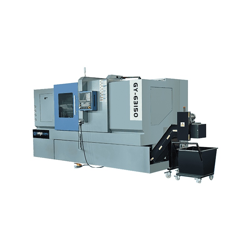
Long shafts and stepped shaft components
Pipe fittings, flanges, and larger connection parts
Oil, gas, and hydraulic industry components
General machinery and heavy equipment parts
Batch production of medium and large metal parts
Workpieces that require programmable tailstock support
Slant bed construction for steady cutting and easier chip evacuation
Roller linear guideways for smooth motion and dependable precision
Large spindle bore for bigger bar stock and tube work
Powerful spindle setup for heavy-duty turning tasks
Programmable tailstock for efficient support on long parts
12-station turret for flexible multi-tool machining
Sealed electrical cabinet for harsh workshop conditions
Easy front-side hydraulic adjustment for everyday operation
Practical chip removal design for a cleaner cutting area
| Projects | unit | GY-63150 | |
| PROCESSING CAPACITY | Maximum turning diameter of bed | mm | 680 |
| Maximum rotary diameter of support plate | mm | 450 | |
| Maximum machining length | mm | 1500 One clip and one top | |
| MAIN SHAFT | Spindle end form | \ | A2-11 |
| Diameter of main shaft through hole | mm | 105 | |
| Masimum rod passing diameter | mm | 90 | |
| Maximum spindle speed | r/min | 1600 | |
| Spindle shift mode | \ | Infinitely variable speed | |
| Main motor power | kw | 22 | |
| Chuck type | \ | Hydraulic chucks | |
| Chuck size | mm | 12 inches/15 inches | |
| FEED | X-axis stroke | mm | 720 |
| Z-axis stroke | mm | 1500 | |
| X-axis fast-moving velocity | m/min | 25 | |
| Z-axis fast-moving velocity | m/min | 25 | |
| X-axis motor torque | N·m | 15 | |
| Z-axis motor torque | N·m | 15 | |
| Type of rail | \ | Roller guideways | |
| X-axis guide rail specifications | mm | 45 | |
| Z-axis guide rail specifications | mm | 55 | |
| W-axis guide rail specifications | mm | 35 | |
| X-axis made screw specification | mm | 4010 | |
| Z-axis made screw specification | mm | 5012 | |
| W-axis made screw specification | mm | 4010 | |
| TOOL REST | Tool rest type | \ | 125-12 stations - 480 cutter heads |
| Square tool/Boring tool size | mm | 32*32/φ50 | |
| TAIL SEAT | Tail seat form | \ | Servo tailstock |
| Tail seat sleeve taper | \ | \ | |
| Tail seat sleeve diameter | mm | \ | |
| Tail seat sleeve stroke | mm | \ | |
| OTHER | Machine tool size (length* width* height) | mm | 4500* |
| Machine weight | kg | 9000 | |
| Hydraulic center frame | mm | 50-310 | |
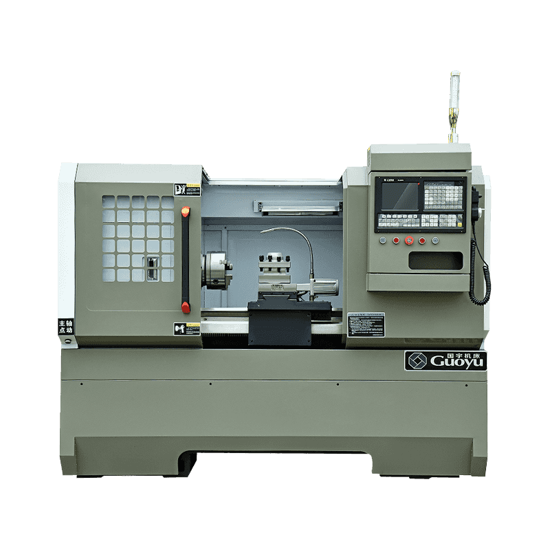
Technical Characteristics: It can cut all kinds of turning surfaces by bicycle, such as conical surf...
See Details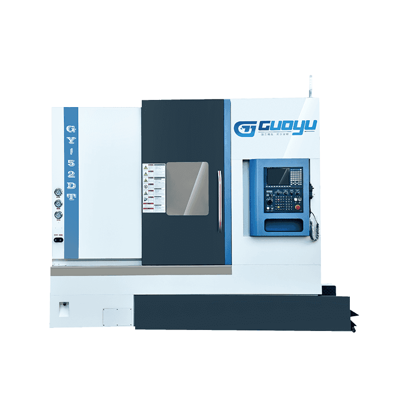
Technical Characteristics: The CNC machine tool for inclined beds adopts the domestic or imported hi...
See Details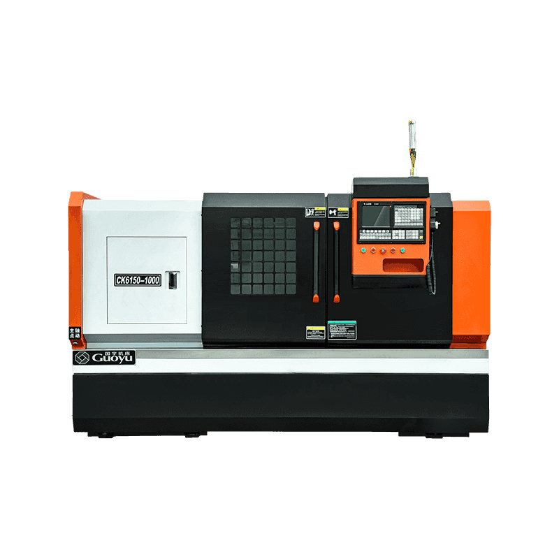
Technical Characteristics: It can automatically turn all kinds of turning surfaces, such as cylinder...
See Details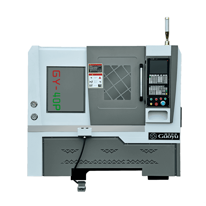
Technical Characteristics: 40P is a kind of small precision machine tool, that is suitable for the e...
See Details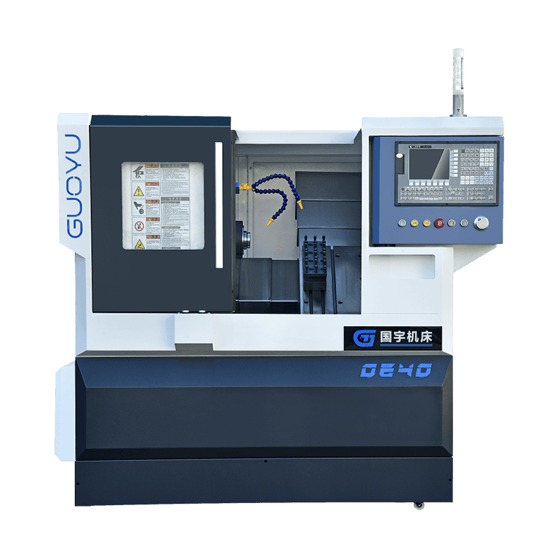
Introducing our Optional Control System CNC Lathe for Metal Processed, a sophisticated and reliable ...
See Details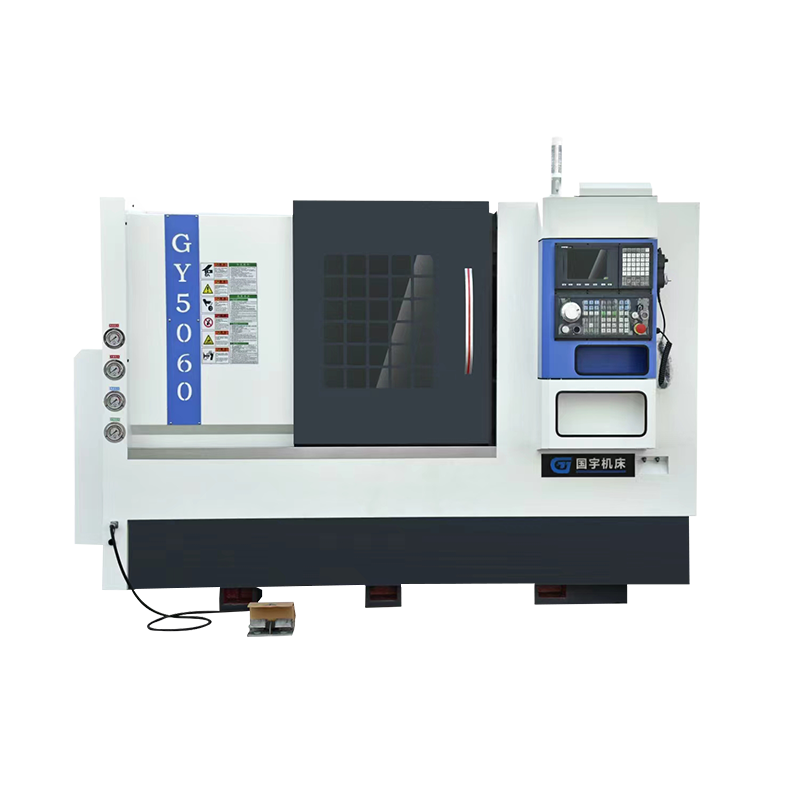
Technical Characteristics: All lathes are integrally cast with 250 materials to ensure processing ri...
See Details


A part that fits perfectly on paper but refuses to seat correctly on the assembly line. A batch of components that pass inspection one week and get rejected the...
READ MORE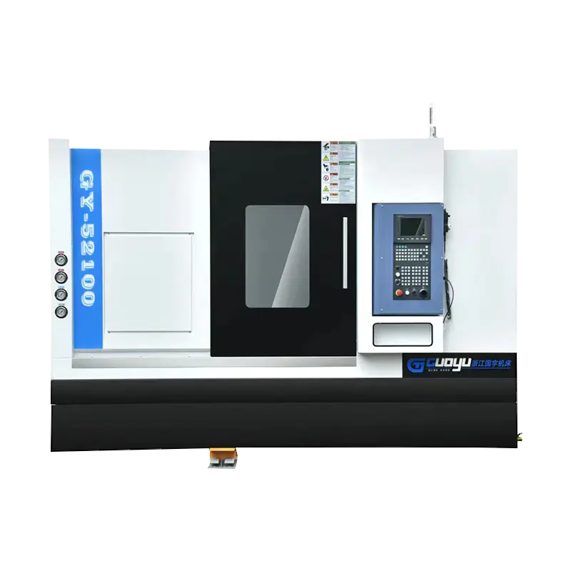
Watching a batch of parts come off a Horizontal Turret Lathe Machine looking completely different from the test piece machined the week before is a familiar hea...
READ MORE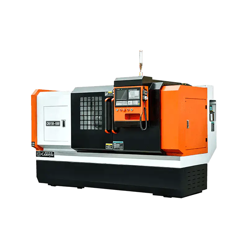
Manufacturing rarely stands still. Schedules get tighter, customers ask for more variety, and the same workshop that used to run three or four part types now ha...
READ MOREA twin spindle twin turret CNC lathe carries two independent spindles—typically arranged face-to-face—and two separate turrets that hold cutting tools. The main spindle grips the raw stock. The subspindle sits on a servo-driven slide, moves forward, and accepts the partially finished part directly from the main spindle. The transfer happens in under two seconds without the operator's hands touching anything.
What makes this "twin turret" different from a standard twin spindle machine? The second turret gives each spindle its own dedicated tool set. While the main spindle runs one set of operations, the subspindle runs a completely different set on a different part. Or both turrets work on the same spindle simultaneously—one roughing while the other finishes.
The machine essentially becomes two lathes sharing one enclosure, but with the critical ability to pass parts between them automatically.
The main advantage is completed-in-one-cycle machining of parts that require work on both ends. But that phrase gets thrown around too loosely. Let me explain what it actually delivers.
Uninterrupted production flow. In a conventional lathe, a part with back-face features needs a second operation. Someone removes the part from the first machine, flips it, loads it into a second machine, or back into the same machine after a program change. That gap between operations kills throughput. The twin spindle twin turret configuration removes the gap entirely. The part moves from the main spindle to the subspindle while the machine keeps cutting. No waiting. No operator intervention. No queue between ops.
Elimination of the accuracy gap. When a human flips a part, the second setup never matches the first exactly. A part that ran true to 0.005 mm on the front face may clock in at 0.02 mm runout after flipping. The operator cannot see that without indicating the part again. A twin spindle transfer references the part from the same machined diameter as the main spindle just created. Concentricity between front and back features holds to whatever the machine's spindle accuracy allows—typically 0.005 mm or better, every part, every shift. That consistency alone justifies the machine for many shops.
Overlapped cycle time reduction. Here is where the twin turret part matters. With two turrets and two spindles, the machine can run fully overlapped cycles. The main spindle finishes the front of Part A and transfers it to the subspindle. While the subspindle machines the back of Part A, the main spindle starts cutting the front of Part B. Two parts in process at once. The cycle time becomes the longer of the two operations, not the sum. For a part with 40 seconds of front work and 30 seconds of back work, the machine produces one completed part every 40 seconds instead of every 70 seconds plus transfer time. That is a 43% reduction in cycle time.
Unattended operation after the first piece. Once the machine runs the first part and the operator verifies dimensions, the machine can run unattended for hours. The automatic transfer handles every subsequent part. No one needs to be there to flip parts, load second operations, or re-indicate workpieces. A single operator can tend two or three of these machines simultaneously.
|
Machine Type |
Automatic Part Transfer? |
Overlapped Cutting on Two Parts? |
Both Turrets on One Spindle? |
Typical Cycle Time Reduction vs. Single Spindle |
Best Application |
|
Single spindle, single turret |
No |
No |
No |
Baseline (0%) |
Small batches, simple parts |
|
Single spindle, twin turret |
No |
No |
Yes (rough/finish simultaneously) |
20–30% |
Parts with heavy material removal |
|
Twin spindle, single turret per spindle |
Yes |
No (each spindle has own turret, but no overlap between parts) |
No |
30–40% |
Back-work required, but simple back features |
|
Twin spindle, twin turret |
Yes |
Yes (both spindles cutting different parts) |
Yes (both turrets on main spindle available) |
40–60% |
Complex parts needing both ends machined, medium to high volume |
The main advantage of a twin-spindle twin-turret CNC lathe is not speed alone. It is the elimination of the second operation as a separate event. Once the machine transfers a part, the subspindle becomes its own little lathe working in parallel. The operator stops being a part flipper and starts being a process manager. For any shop running production quantities of parts that need work on both ends, the shift from sequential to parallel processing changes the entire cost structure of the job.
Zhejiang Guoyu CNC Machine Tool Co., Ltd. relies on rich experience, professional technology and advanced methods to ensure the quality of its products, so that customers can enjoy more professional and thoughtful service.
 [email protected]
 +86-15356565970
 Xialiang Industrial Area, Luqiao District, Taizhou City, Zhejiang Province, China
Copyright © Zhejiang Guoyu CNC Machine Tool Co., Ltd. All Rights Reserved.

Wholesale Precision CNC Lathe With Programmable Tailstock For Connected Inclined Rail Tool Tower Suppliers