English
 中文简体
中文简体 русский
 Español

The Conjoined 35° Oblique Rail Cutter Tower Tail Seat Precision CNC Horizontal Lathe is a really pra...
See DetailsA machined part can look genuinely simple on a drawing and still create very different requirements once it hits the shop floor. A change in aperture size, slot position, contour shape, or overall length can alter how the part gets held, where the tool can actually reach, and how the machining path needs to be arranged from start to finish.
This is particularly relevant to Precision CNC Lathe work, where small geometry changes can affect several operations at once without much warning. A deeper internal opening may require a genuinely different approach from a shallow one sitting nearby. A narrow slot can change tool access in ways that ripple through the whole plan. A long section can create different support needs from a short, compact part that behaves nothing like it.
For engineers and production teams, geometry is therefore a lot more than a drawing feature to check off a list. It influences how the part moves through machining, how tools approach each area in turn, and how different operations get coordinated with one another across the whole job.
An aperture may look like a simple feature at a glance, but its size and position can affect how internal areas are machined. As the opening changes, the available access for internal machining changes with it, sometimes in ways that are not immediately obvious.
A relatively open internal area may allow easier tool access without much fuss. A smaller opening can restrict the path and make internal machining a lot more sensitive to the relationship between the tool and surrounding material pressing in close.
The shape of the aperture also matters quite a bit here. A round opening presents a genuinely different machining situation from an opening that changes along its length or connects with another feature further in.
Engineers may need to consider several points together before finalizing a plan.
These factors can influence the machining sequence in ways that aren't always obvious from the drawing alone.
For example, an internal feature may need to be completed before another external feature makes access a lot more difficult later on. Changing the aperture can therefore affect more than one operation, even when the rest of the part remains completely unchanged on paper.
For a High-Precision CNC Lathe, this relationship becomes particularly relevant when a component contains several connected internal and external features stacked close together. The machining plan needs to account for the complete geometry, rather than treating each opening as an isolated detail sitting on its own.
Slots create another type of geometry challenge that shows up more often than people expect. Unlike a continuous cylindrical surface, a slot interrupts the surrounding material and introduces a localized feature that may require a genuinely different tool path to reach properly.
The position of the slot matters a great deal here. A slot close to another feature can reduce available working space noticeably. A slot placed farther away may allow a lot more straightforward approach without extra planning.
Its orientation can also change the machining path considerably. A slot that follows one direction may get reached quite differently from one positioned across another surface nearby. When several slots are present on the same part, their relationship to each other can influence the order in which the machine approaches them.
| Slot Characteristic | Possible Machining Consideration |
|---|---|
| Position | Affects tool access |
| Width | Influences tool selection |
| Depth | Changes the required cutting path |
| Orientation | Can alter the approach direction |
| Relationship with other features | May affect machining sequence |
The surrounding geometry should get considered at the same time as the slot itself, not separately. For example, a slot near an edge may leave more open space on one side but create a genuinely different holding requirement on the other. A slot surrounded by other features may require a lot more careful planning to prevent interference between the tool and the part as it moves.
This is why adding or moving a slot can sometimes require changes to an existing machining program that already worked fine before.
Contours can change gradually along the surface, rather than following a simple straight profile the tool can just trace. This means the tool path needs to follow the changing shape of the part step by step, adjusting as it goes.
A small change in a contour can influence where the tool enters, travels, and leaves the material at each stage. If the contour connects with another surface, the transition between the two areas also becomes part of the machining consideration worth planning for.
Simple external profiles may allow a relatively direct path with few surprises. More varied contours can require several changes in tool movement along the way instead.
The same principle applies just as much to internal contours. An internal curved surface can create genuinely different access requirements from an external curve, because the surrounding material limits the available space a lot more tightly. The tool has to reach the intended area without interfering with nearby geometry crowding the space.
A High Precision CNC Lathe can therefore be used for parts with changing profiles, but the part geometry still determines how the machining work actually needs to be arranged in practice.
Designers can make the process a lot easier to plan by considering whether each contour serves a genuine functional purpose and whether its transition with nearby surfaces is practical to machine without extra headaches.
A contour that looks visually minor on a drawing may have a genuinely noticeable effect once the tool path actually gets created for real.
Part proportions can change quite a bit how machining needs to be organized from the very start. A short, compact component may behave genuinely differently during machining from a long component with a relatively small diameter running through it. As the length of the part increases compared with its cross-section, support and tool movement become a lot more important considerations to work through.
The issue isn't simply the total length by itself. The distribution of material along the part matters just as much. A long section with a consistent shape creates a genuinely different machining situation from a part that combines a long narrow section with larger features sitting at either end.
The position of the machining area also matters here. Work performed close to a supported section may create quite different conditions from work carried out farther away from any support at all.
Engineers can therefore look at several factors together before locking in a plan.
These details can genuinely influence how the part gets arranged during machining, more than a quick glance at the drawing might suggest.
A geometry change that makes one section longer may appear minor from a design perspective sitting at a desk. In production, though, that change can require a genuinely different approach to holding, tool movement, and operation order once it hits the floor.
For precision machining, the relationship between part proportions and machining arrangement should be considered during design, rather than after the drawing has already been finalized and sent along.
Complex structures often combine several features within a fairly small area, packed close together with little room to spare. A single component may contain apertures, steps, grooves, slots, shoulders, and changing contours all within the same few inches of material.
When these features interact, the machining path becomes a lot more dependent on their positions relative to one another, rather than each feature standing on its own.
Consider a part with an internal opening and an external slot near the same area. The two features may each be fairly straightforward when viewed separately on their own. Their combination, though, can create a genuinely more restricted working area once both are in play together.
This is where feature relationships become genuinely important to think through.
| Geometry Combination | Possible Effect on Machining |
|---|---|
| Aperture and nearby slot | May restrict tool access |
| Long section and changing contour | May alter tool movement |
| Multiple grooves | Can require different approach paths |
| Internal and external features | May influence operation order |
| Closely spaced surfaces | Can reduce available working room |
The machine doesn't simply follow the drawing as a single continuous movement from one end to the other. The geometry has to be translated into a sequence of workable paths that actually make sense on the floor.
That sequence can shift considerably when the part design changes even slightly. A new groove may require an additional operation tacked onto the plan. Moving a shoulder may change where another tool can actually enter the part. Changing the depth of an internal feature may affect how an existing path reaches the area at all.
This is why complex geometry should get reviewed as a connected structure, rather than as a collection of individual features considered one at a time in isolation.
Machining paths are closely tied to the shape of the material that actually needs removing, more than people sometimes realize. When a part has a simple profile, the tool can often follow a relatively direct route without much adjustment. When the profile contains multiple transitions, recesses, openings, or interrupted surfaces, the path can become genuinely more varied and harder to plan cleanly.
Different geometry can require changes across several areas at once.
This doesn't mean that every complex part requires a completely different production method built from scratch. Some geometry changes can get absorbed into an existing process without much trouble, while others affect several stages at once and demand a rethink.
The important issue is identifying which changes actually have a wider effect down the line. For example, changing the position of a groove may affect only one local operation, if there's sufficient access around it already. Changing that same groove so it overlaps another feature, though, can alter the relationship between several machining paths at once.
A Precision CNC Lathe process therefore needs consideration in terms of geometry and path interaction together, not separately. The shape of one feature can genuinely determine how another feature gets approached later in the sequence.
Machining sequence is often shaped by access more than anything else. A feature that's easy to reach at the beginning of production may become genuinely harder to reach after surrounding material has been removed, or after another feature has already been created nearby. This can make operation order a genuinely important part of engineering planning worth getting right early.
A useful way to examine a revised part is asking how each geometry change affects the operations sitting around it.
This approach is particularly useful when a part goes through several design revisions in a row, each one adding small changes that compound.
A change in aperture depth may affect internal machining down the line. A new slot may affect tool access unexpectedly. A longer section may change support needs entirely. A modified contour may require a revised movement path that wasn't needed before.
Each change should therefore get traced through the production process itself, instead of being evaluated only from the drawing sitting on a screen. This can also help communication between design and manufacturing teams considerably. When a geometry change has a clear machining consequence, that consequence can get discussed openly before production planning is actually finalized and locked in.
Part geometry doesn't need to be simplified at the expense of function just to make machining easier. The more useful approach is understanding how each feature will interact with machining access and production steps, then designing around that understanding.
A practical design review can look at the part from several directions at once.
Apertures. Check whether internal features can be reached through the available opening and whether nearby geometry creates restrictions worth flagging early.
Slots. Consider their position, orientation, and relationship with surrounding surfaces carefully. A slot should be evaluated as part of the complete local geometry, not on its own.
Contours. Look at how changing surfaces connect with neighboring features throughout the part. Smooth transitions may require genuinely different paths from straight sections nearby.
Length ratios. Review how long or narrow sections affect support and machining location across the whole piece.
Complex structures. Check whether several small features overlap in ways that make tool access more difficult than the geometry may suggest.
Machining paths. Consider whether a geometry change affects only one operation or creates changes across several paths at once.
For a High-Precision CNC Lathe, these questions can be especially useful when a part contains several interacting features positioned close together. Precision machining is not only about how the machine moves on its own. The geometry of the part also influences which movements are practical during machining.
The same thinking applies when a design moves toward a High Precision CNC Lathe production process further down the line. A drawing may specify the finished shape clearly enough, but production teams still need to translate that shape into accessible operations, suitable tool paths, and a genuinely workable sequence that holds up on the floor.
When engineers review geometry this way, design changes become a lot easier to assess before they cause problems. A modified aperture, additional slot, longer section, or revised contour can get traced through the machining process to see exactly where the real production impact actually occurs.
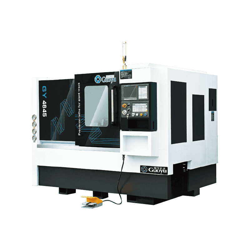
The Conjoined 35° Oblique Rail Cutter Tower Tail Seat Precision CNC Horizontal Lathe is a really pra...
See Details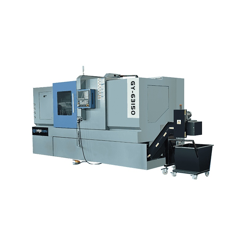
The Precision CNC Lathe With Programmable Tailstock For Connected Inclined Rail Tool Tower is just a...
See Details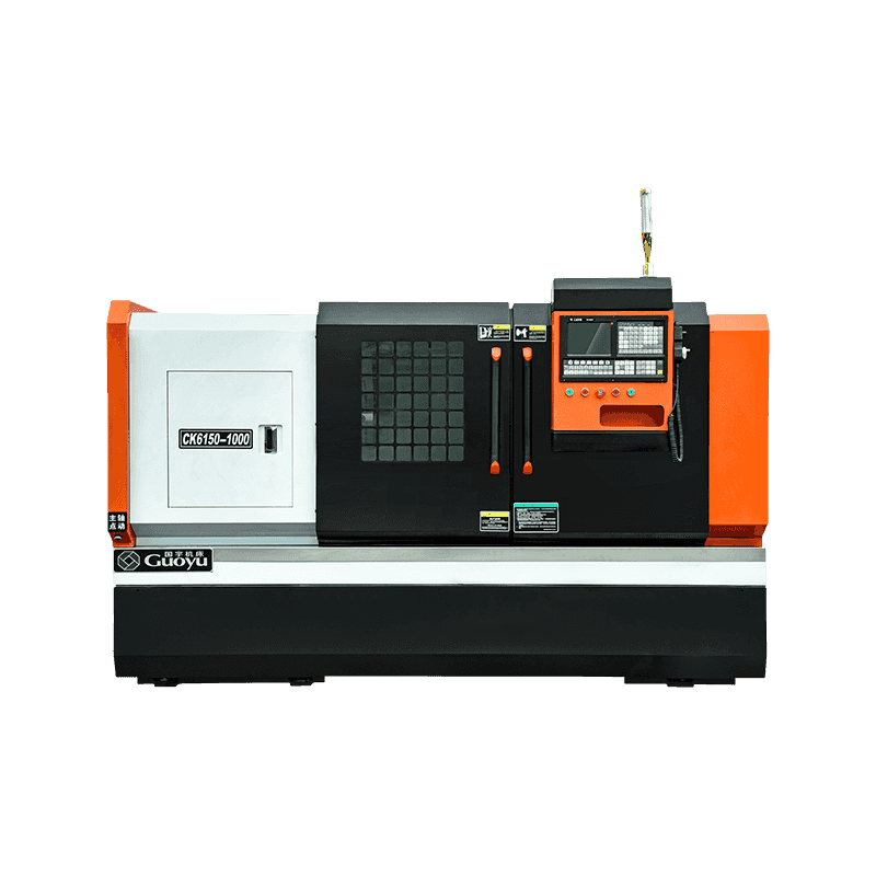
The Heavy Cutting Hard Guideway CNC Lathe For Metal Cutting is a really tough, heavy-duty machining ...
See Details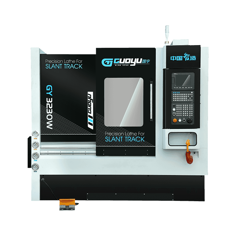
Technical Characteristics: The machine tool is of high precision, and the spindle is supported by hi...
See Details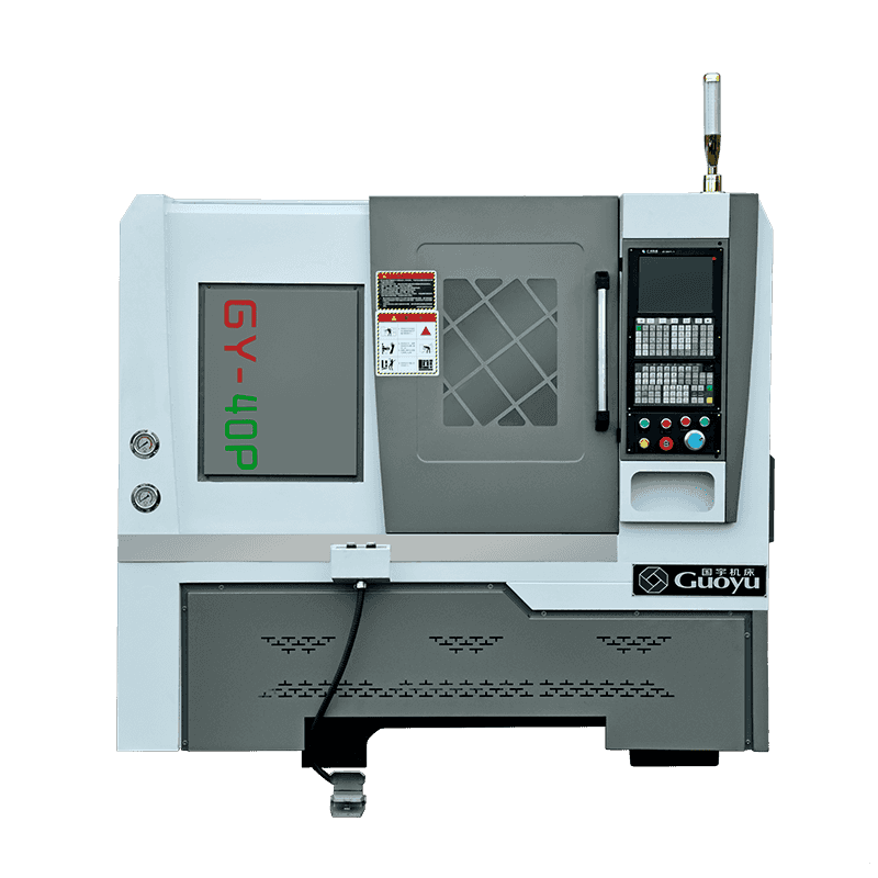
Technical Characteristics: 40P is a kind of small precision machine tool, that is suitable for the e...
See Details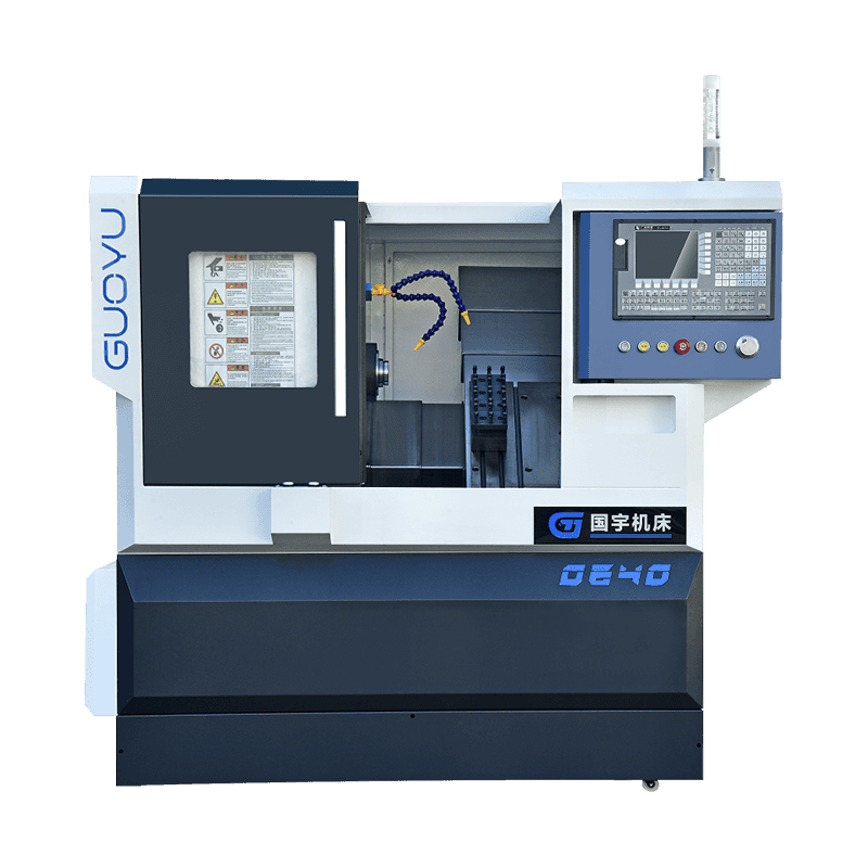
Introducing our Optional Control System CNC Lathe for Metal Processed, a sophisticated and reliable ...
See Details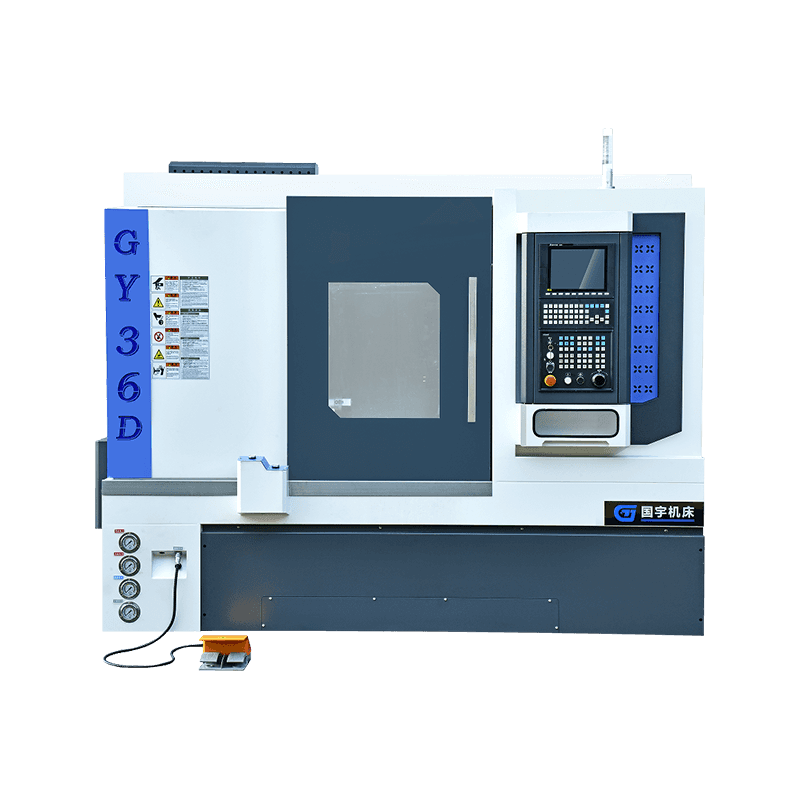
Technical Characteristics: All lathes are integrally cast with 250 materials to ensure processing ri...
See Details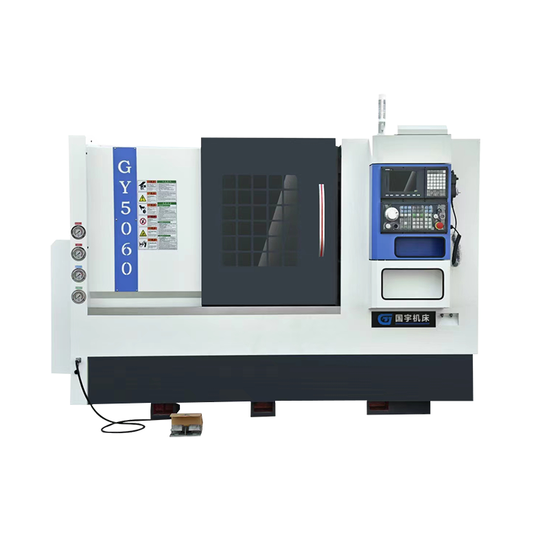
Technical Characteristics: All lathes are integrally cast with 250 materials to ensure processing ri...
See DetailsOur team of digital and business experts will guide you to the right direction.
Let's Talk
Zhejiang Guoyu CNC Machine Tool Co., Ltd. relies on rich experience, professional technology and advanced methods to ensure the quality of its products, so that customers can enjoy more professional and thoughtful service.
 [email protected]
 +86-15356565970
 Xialiang Industrial Area, Luqiao District, Taizhou City, Zhejiang Province, China
Copyright © Zhejiang Guoyu CNC Machine Tool Co., Ltd. All Rights Reserved.