

 English
 中文简体
中文简体
 русский
 Español

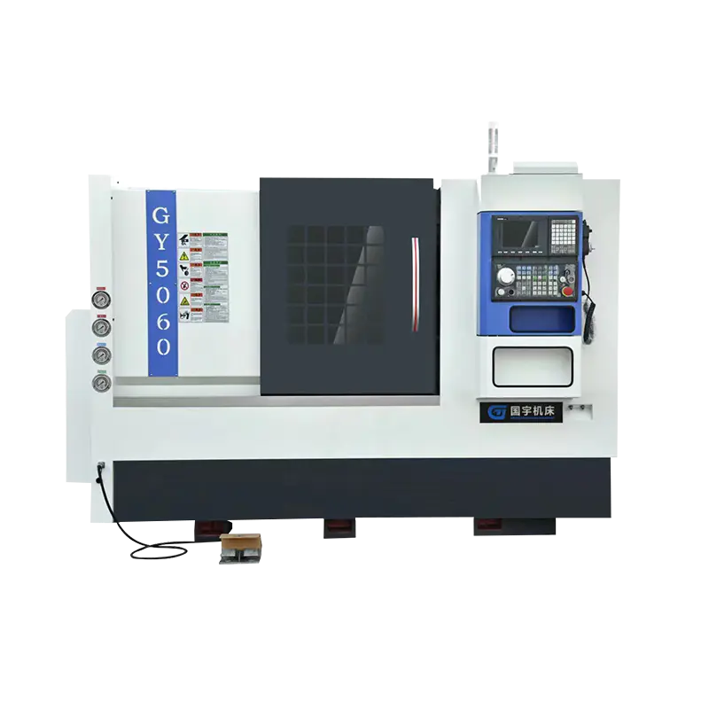
Technical Characteristics: It can cut all kinds of turning surfaces by bicycle, such as conical surf...
See DetailsInstallation errors in large machine tool setups rarely announce themselves at the moment they happen. A lathe that appears to run correctly after commissioning may still produce parts with subtle taper, inconsistent surface finish, or dimensional deviation. These issues might only become apparent once the production run is underway or during quality inspection. By that point, the machine is anchored, tooling is set, and tracing the problem back to an installation decision takes time—time that production schedules rarely allow. For factories investing in a Heavy Duty CNC Lathe Machine, the installation phase is not a logistics formality that ends when the equipment reaches the floor. It is a technical process that determines whether the machine will perform to its rated accuracy for years, or spend its service life compensating for conditions that were set incorrectly at the very beginning.
Standard CNC lathes and heavy-duty machines share the same mechanical principles, but the engineering considerations at installation diverge considerably once machine weight and workpiece loads increase beyond a certain threshold.
A heavy-duty lathe places substantial concentrated load on the floor beneath it. The bed casting, headstock assembly, and any workpiece mounted during machining combine into a static load that standard factory flooring may not distribute evenly. Where a lighter machine tolerates minor floor irregularities without significant performance consequence, a heavy machine amplifies any unevenness in floor support into measurable bed distortion — distortion that shows up directly as machining error.
Vibration behavior is the other critical difference. Heavier machines generate more vibration energy during cutting, particularly during interrupted cuts, heavy roughing operations, or face milling with large cutters. That energy, if not absorbed at the foundation level, transmits through the machine structure and affects surface finish quality, tool life, and spindle bearing condition progressively over time.
These two factors — floor loading and vibration transmission — define the installation requirements that go well beyond what standard guidance for smaller CNC equipment covers.
Site preparation should be completed before the machine is delivered, not adjusted around its final resting position. Attempting to address foundation or environmental deficiencies after the machine is placed creates work that is simultaneously harder and more disruptive.
Floor load assessment is the starting point. The factory floor needs to carry the full machine weight plus the heaviest workpiece that will be mounted during operation. For very heavy configurations, a dedicated reinforced concrete foundation pad is often required rather than relying on the existing factory slab. The foundation design should account for the machine footprint, anchor bolt positions, and the depth needed to achieve adequate load bearing without future settlement.
Environmental condition checks should cover:
Handling route planning matters specifically for heavy equipment. The path from the delivery point to the final installation position needs to support the machine weight throughout transit across the floor. Floor features like expansion joints, drainage grates, or cable trenches must be identified early so that bridging or route adjustments can be arranged without delays on delivery day.
The concrete foundation beneath a heavy-duty lathe is not simply a stable platform. It functions as a vibration isolation and load distribution system, and its design affects machine performance directly. Inadequate foundation work is one of the more common root causes of accuracy problems that persist despite repeated leveling attempts — the kind of fault that is frustrating precisely because it cannot be fixed from above.
Key considerations in foundation design:
Concrete grade and curing time: The foundation must use structural concrete with an adequate strength specification and must be fully cured before machine installation begins. Concrete that has not cured completely continues to settle and shrink after the machine is placed, causing leveling to drift in the weeks following commissioning.
Anchor bolt placement accuracy: Foundation anchor bolt positions must correspond exactly to the machine base plate layout. Positional errors force compromise during installation and introduce stress into the machine base that is difficult to eliminate afterward.
Vibration damping layer: In environments with significant ambient vibration from adjacent equipment, an anti-vibration pad or isolation layer between the machine base and the foundation surface reduces transmission into the machine structure.
Foundation isolation gap: In some installations, the machine foundation is physically separated from the surrounding factory slab by an isolation gap filled with damping material. This prevents vibration generated by nearby equipment from traveling through the slab and into the lathe.
The foundation should always be designed using the machine manufacturer's installation drawing, which specifies load points, anchor positions, and concrete requirements for that specific model.
Moving a heavy machine to its final position requires specialized lifting equipment and careful sequencing. Errors in positioning before anchoring can require the machine to be relocated — a costly and potentially damaging outcome that proper planning avoids.
Transportation to position:
Initial positioning checks:
Anchor bolt installation:
Foundation anchor bolts are typically set in cast sleeves that allow positional adjustment before final grouting
The machine sits on leveling screws or wedge pads during this phase, not directly on the foundation surface
Anchor bolts are tightened progressively and uniformly across all positions — tightening individual bolts to full torque in sequence introduces asymmetric stress into the machine base
Leveling is the installation step directly connected to machining accuracy. A new CNC heavy duty lathe that leaves commissioning without correct leveling will produce parts with systematic errors — taper on turned diameters, deviation on faced surfaces — that cannot be fully resolved through control compensation. The geometry of the machine is set at installation, and the control system works within that geometry, not around it.
The machine bed is a precision-ground structure. When the machine is correctly leveled, that structure sits in the configuration it was manufactured and tested in at the factory. When it is not, the bed experiences torsional distortion that shifts the geometric relationships between the spindle axis, the carriage guideways, and the tailstock centerline.
Leveling procedure, step by step:
Mechanical installation addresses only one dimension of commissioning. Electrical, hydraulic, and coolant systems each require their own connection and verification sequence before any test running begins.
Electrical connections:
Hydraulic system setup:
Coolant system:
Commissioning is the verification phase — confirming that the installed machine achieves the performance it was specified to deliver. For a new CNC lathe factory-built to heavy-duty specifications, this follows a structured sequence that moves from basic function checks to precision verification.
Axis movement verification:
Spindle verification:
Test cutting sequence:
Surface finish and vibration check:
Understanding what goes wrong during installation — and what symptoms those errors produce — helps engineering teams recognize problems early and evaluate whether a machine is performing to its potential or masking a setup error.
| Installation Error | Immediate Consequence | Long-Term Effect |
|---|---|---|
| Insufficient foundation strength | Settlement after installation | Leveling drifts — accuracy degrades progressively |
| Uneven anchor bolt tightening | Bed distortion from asymmetric stress | Systematic taper or straightness deviation |
| Electrical phase sequence error | Motor rotation reversal | Spindle or drive damage on startup |
| Hydraulic air not purged | Erratic actuator response | Inconsistent chuck clamping, chatter |
| Leveling not rechecked after anchoring | Residual bed twist | Taper on turned diameters |
| Tailstock not realigned after leveling | Tailstock centerline offset | Taper on workpieces machined between centers |
| Inadequate vibration isolation | Ambient vibration transmitted into structure | Surface finish degradation, accelerated bearing wear |
| Coolant system not purged before cutting | Air pockets in coolant flow | Intermittent coolant delivery, thermal instability |
Each of these errors is preventable with a systematic installation procedure. Most are also genuinely difficult to diagnose after production has started, when machining errors tend to get attributed to tooling wear, programming issues, or material variation before anyone thinks to question the installation.
The quality of installation support from a supplier is a meaningful differentiator — particularly for heavy-duty equipment where the process is technically demanding and the consequences of errors reach far into production performance.
A capable CNC lathe supplier should be prepared to provide:
A CNC lathe factory that provides thorough installation documentation and on-site commissioning demonstrates confidence in the machine's accuracy and genuine commitment to the customer's successful operation. Evaluating this support capability during procurement — rather than discovering its absence after delivery — is one of the more practical ways to assess supplier quality beyond the specification sheet.
A heavy-duty CNC lathe that is correctly installed — built on an adequate foundation, leveled within specification, with properly connected and verified systems, and a completed test cut program — begins its service life positioned to deliver the accuracy and reliability it was engineered for. One that moves through installation quickly to meet a production startup deadline may run at the outset, but carries hidden accuracy compromises that affect part quality and maintenance demands from the beginning. The engineering attention required during installation is modest relative to the cost of the machine and the cumulative cost of ongoing machining errors or unplanned downtime caused by problems that trace back to setup. For manufacturing teams commissioning new equipment, the installation phase deserves the same rigor as machine selection and process planning. Zhejiang Guoyu CNC Machine Tool Co., Ltd. supports customers throughout the installation and commissioning process for Heavy Duty CNC Lathe Machines. The company provides technical documentation, qualified on‑site commissioning engineers, and the application knowledge needed to ensure each machine reaches its rated accuracy from the day production begins. If your team is planning a new machine installation or evaluating a CNC lathe supplier's technical support depth, sharing your project details is a productive place to begin that conversation.
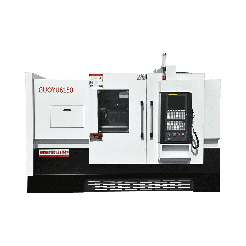
Technical Characteristics: It can cut all kinds of turning surfaces by bicycle, such as conical surf...
See Details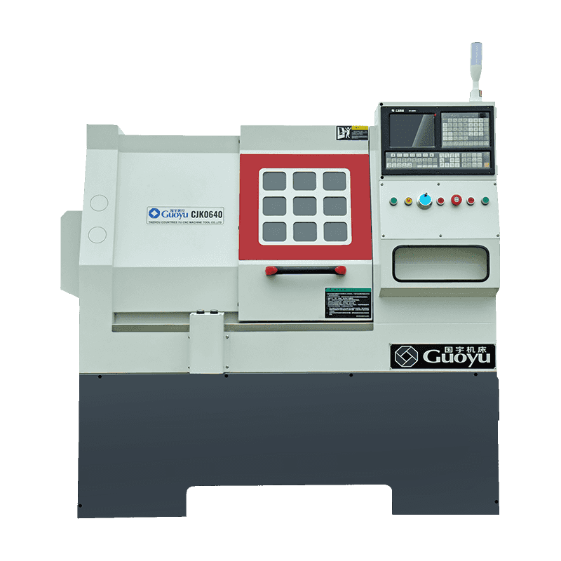
Technical Characteristics: The machine tool is equipped with a quantitative automatic lubrication sy...
See Details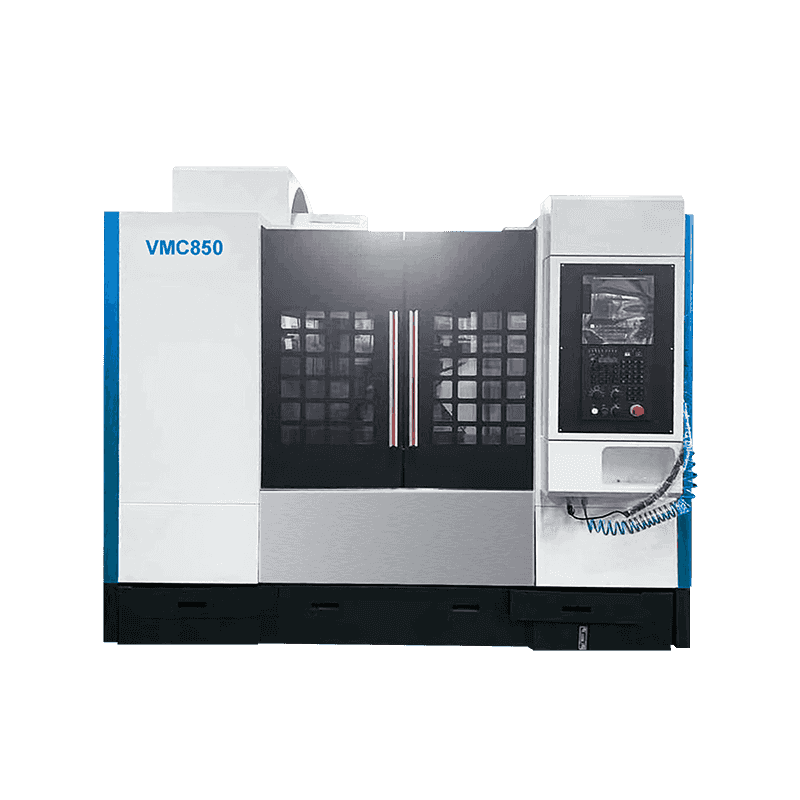
Technical Characteristics The machine tool is a single-column vertical guideway structure. The colum...
See Details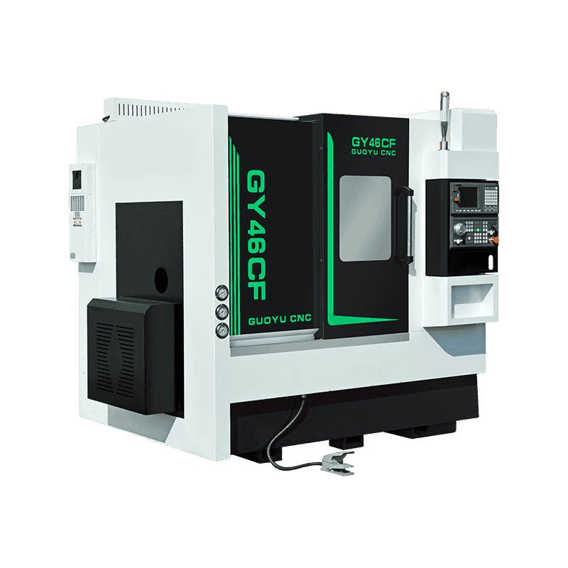
Technical Characteristics: 45° slant bed base structure, with strict aging treatment, smooth chip re...
See Details
Technical Characteristics: The machine tool is of high precision, and the spindle is supported by hi...
See Details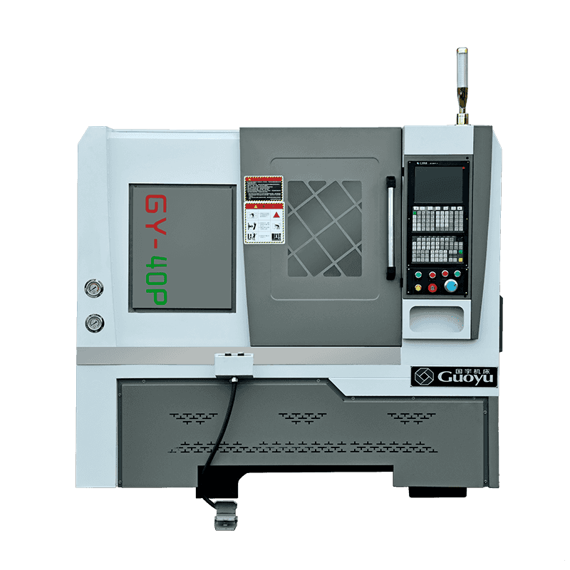
Technical Characteristics: 40P is a kind of small precision machine tool, that is suitable for the e...
See Details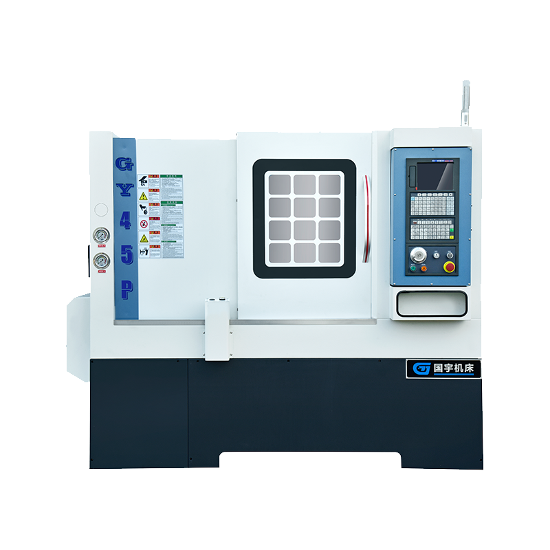
Technical Characteristics:Based on international advanced technology, the design of this machine too...
See Details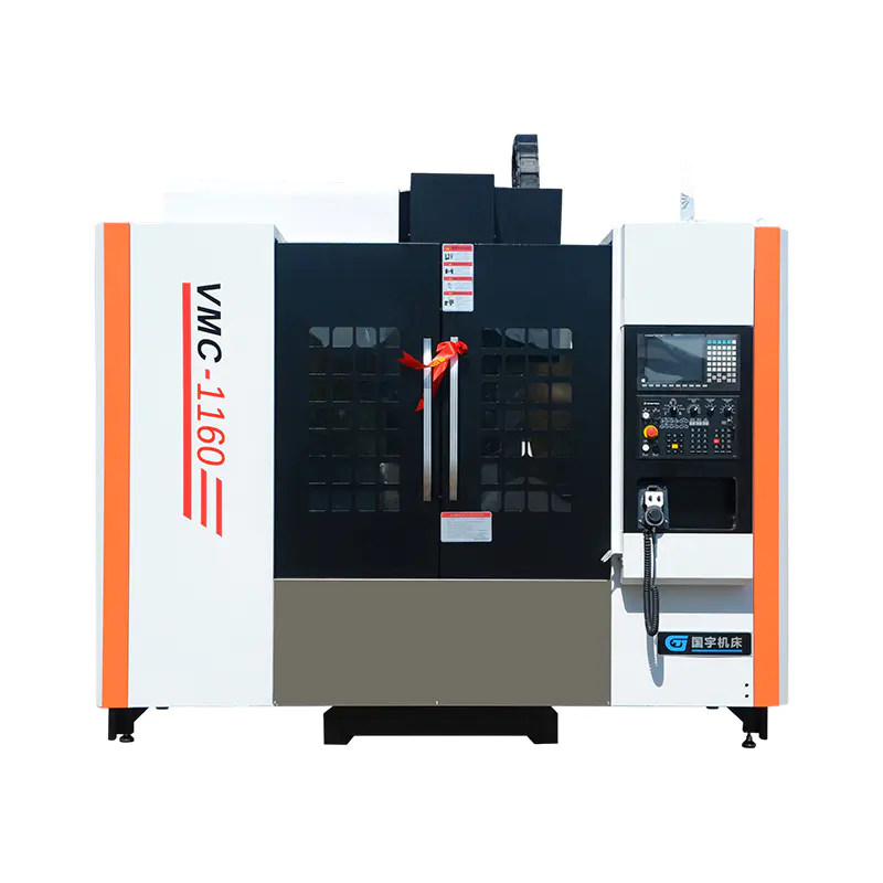
After-sales service commitment: 1. From the date of acceptance, the machine tool host is under warra...
See DetailsOur team of digital and business experts will guide you to the right direction.
Let's TalkZhejiang Guoyu CNC Machine Tool Co., Ltd. relies on rich experience, professional technology and advanced methods to ensure the quality of its products, so that customers can enjoy more professional and thoughtful service.
 [email protected]
 +86-15356565970
 Xialiang Industrial Area, Luqiao District, Taizhou City, Zhejiang Province, China
Copyright © Zhejiang Guoyu CNC Machine Tool Co., Ltd. All Rights Reserved.